
Hydronic floor heating system with adaptive fluid circuit

Inactive Publication Date: 2009-01-15
BUX & CO
View PDF14 Cites 18 Cited by
  • Summary
  • Abstract
  • Description
  • Claims
  • Application Information

AI Technical Summary

Benefits of technology

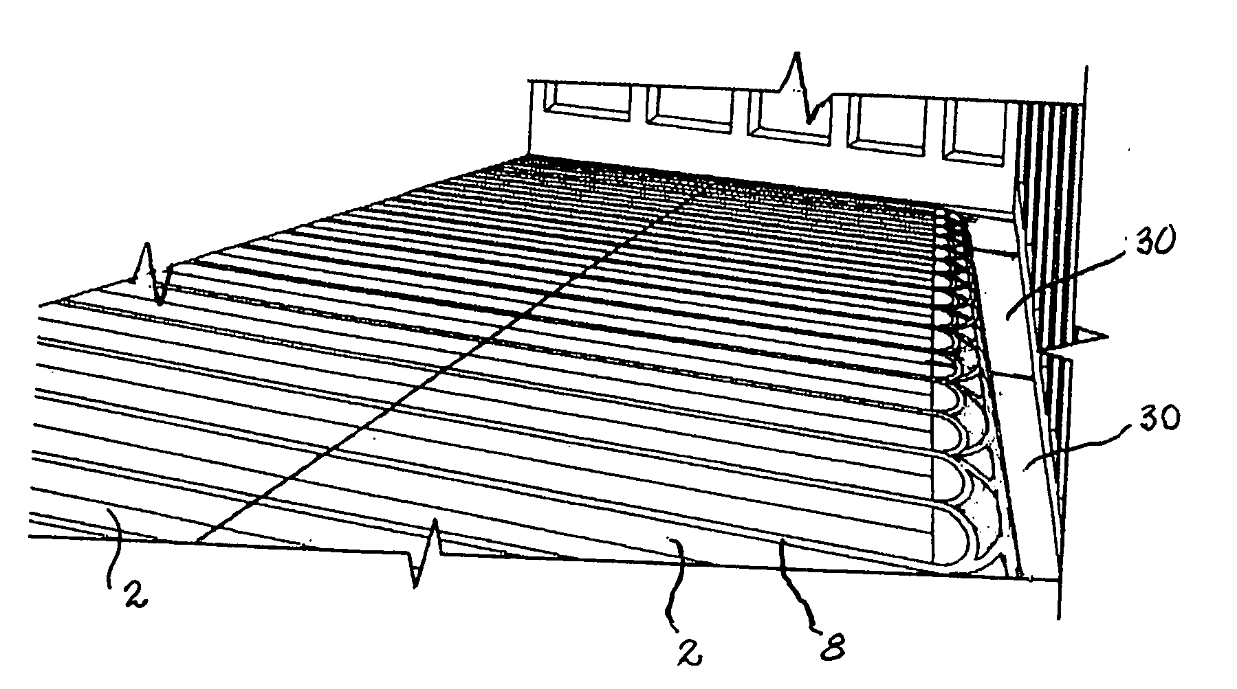
[0023]In addition, the prior art teaches heating systems which conducts hot water through tubing in a series circuit. This obviously leads to gradual cooling of the water as it travels through the tubing, thus creating a thermal gradient across the floor. The presently described apparatus provides a solution to this problem, creating faster and more uniform heat dispersal, by enabling the tubing to be run in both series and parallel circuits and with a circuit density as desired.
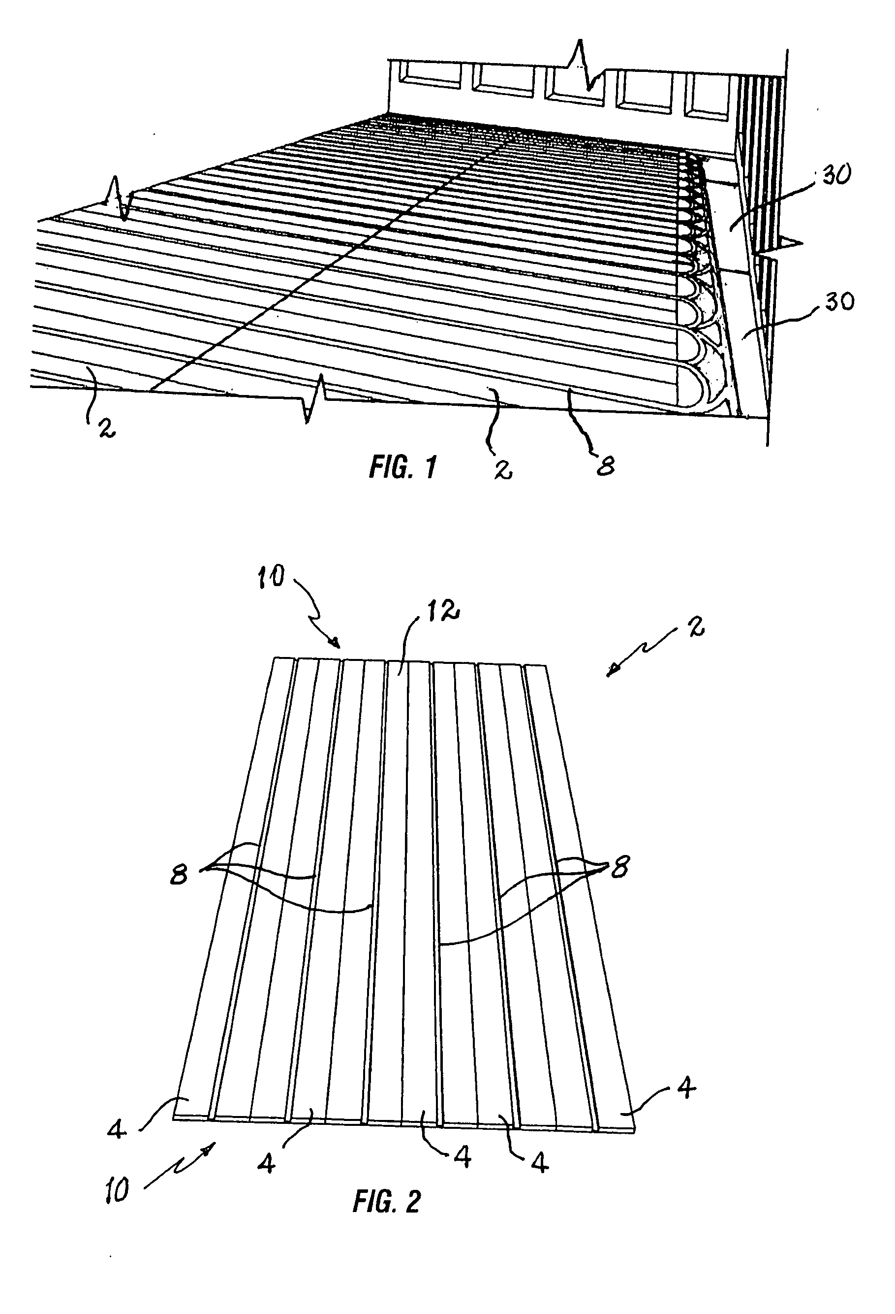
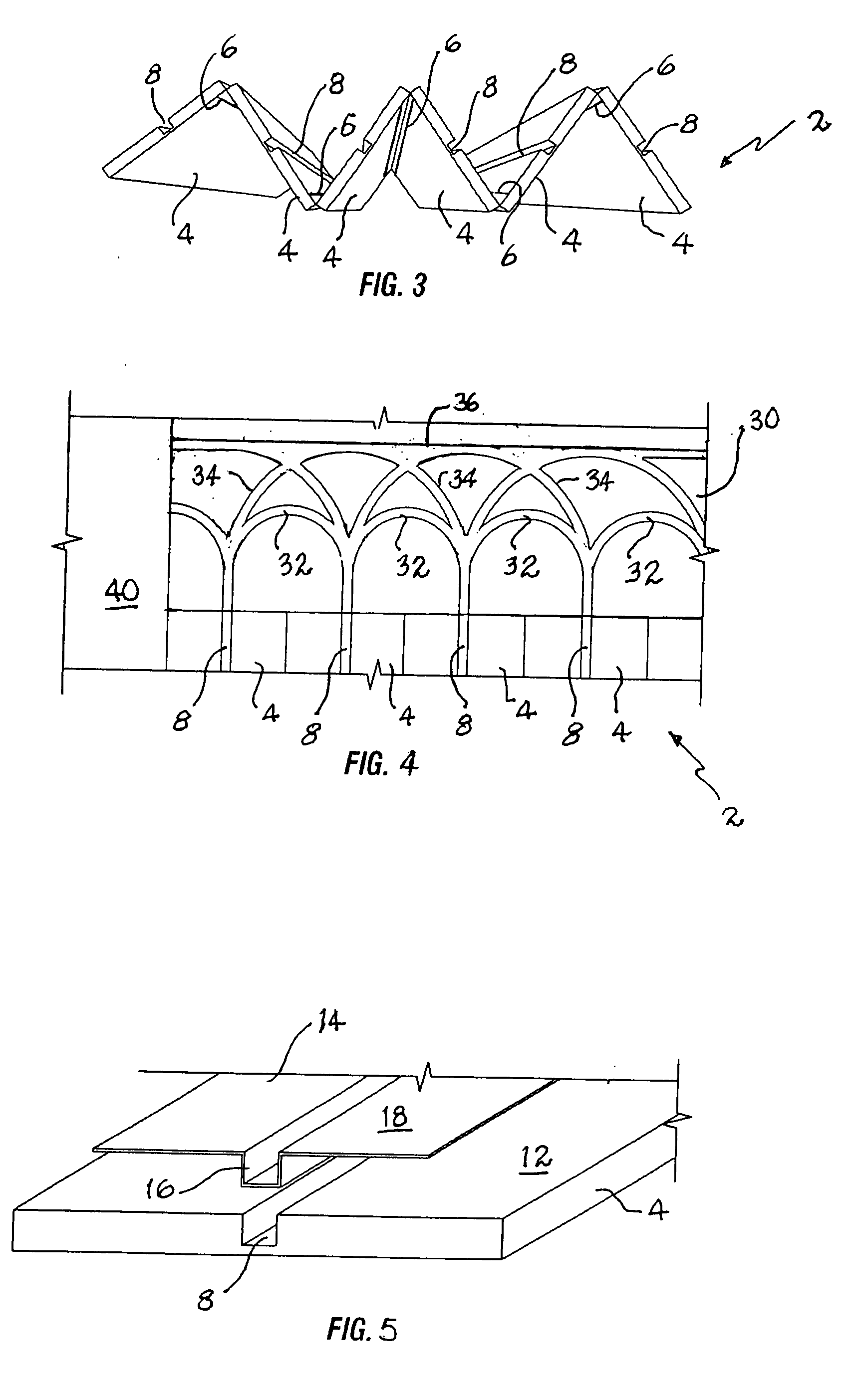
[0024]The present invention uses flat foldable heating panels that are placed in adjacency and fastened over a supporting sub-floor. These heating panels receive conducting tubes for the transfer of heating fluids, and transition panels provide selective configuration of the fluid flow between panels. The heating panels are segmented for folding in a stacked arrangement for easy transport and installation.
[0027]A still further objective is to provide a hydronic floor heating system that is easily transported.
[0029]An even further objective is to provide such a floor heating system for which installation is relatively easy and inexpensive.

Problems solved by technology

However, as mentioned above, much of the prior art discloses heating panels which tend to be difficult to store and transport due to their size.
This, in turn, can make storage, transportation, and installation rather expensive.
This obviously leads to gradual cooling of the water as it travels through the tubing, thus creating a thermal gradient across the floor.

Method used


Image

  • Hydronic floor heating system with adaptive fluid circuit
  • Hydronic floor heating system with adaptive fluid circuit
  • Hydronic floor heating system with adaptive fluid circuit

Examples


Embodiment Construction

[0038]The above described drawing figures illustrate the described apparatus and its method of use in at least one of its preferred, best mode embodiment, which is further defined in detail in the following description. Those having ordinary skill in the art may be able to make alterations and modifications to what is described herein without departing from its spirit and scope. Therefore, it must be understood that what is illustrated is set forth only for the purposes of example and that it should not be taken as a limitation in the scope of the present apparatus and method of use.

[0039]Described now in detail, and illustrated in the figures, is a preferred embodiment of the present invention, a hydronic floor heating apparatus adaptable to various installation sizes and fluid conducting circuit arrangements as a system. The apparatus is modular comprising a plurality of heating and transition panels and fluid conductors. Heating panels 2 (FIG. 2) are each made up of a plurality o...


PUM


Abstract

A room heating apparatus uses separate heating panels fastened to a sub-floor to conduct a heating fluid which then adjusts the temperature of a room. The panels carry fluid tubing and transition panels conduct this tubing between the heating panels. The transition panels have a plurality of grooves that allow the selection of how the tubing is conducted between the heating panels so that a custom heating circuit may be formed to optimize the heating pattern of each installation.

Description

CROSS-REFERENCE TO RELATED APPLICATIONS[0001]Not applicable.STATEMENT REGARDING FEDERALLY SPONSORED RESEARCH OR DEVELOPMENT[0002]Not applicable.THE NAMES OF THE PARTIES TO A JOINT RESEARCH AGREEMENT[0003]Not applicable.INCORPORATION-BY-REFERENCE OF MATERIAL SUBMITTED ON A COMPACT DISC[0004]Not applicable.REFERENCE TO A “MICROFICHE APPENDIX”[0005]Not applicable.BACKGROUND OF THE INVENTION[0006]1. Field of the Present Disclosure[0007]This disclosure relates generally to heating systems for living and working spaces and more particularly to a hydronic floor heating system adaptable to a wide range of circuit configurations.[0008]2. Description of Related Art Including Information Disclosed Under 37 CFR 1.97 and 1.98[0009]Williams, U.S. Pat. No. 3,037,746 discloses a floor covering for radiant heating installations, utilizing tiles for installation against a flat surface such as a floor, wall, ceiling, etc. for covering a heating element overlying that surface. The objectives of this in...

Claims


Application Information

Patent Timeline
IPC IPC(8): F24D3/16F24H9/06
CPCF24D3/142F24D3/148Y02B30/00
Inventor FOO, MENG YEOWMING FOO, TIMMY SZE
Owner BUX & CO
Learn More