
Photovoltaic Modules Having a Filling Material

a photovoltaic module and filling material technology, applied in the field of photovoltaic module construction and photovoltaic module, can solve the problems of shunting across the junction, pinholes and similar flaws affecting the occurrence of large planar solar cells, etc., and achieve the effect of maximizing the amount of light incident and reducing the amount of reflection

Inactive Publication Date: 2009-01-15
SOLYNDRA RESIDUAL TRUST
View PDF49 Cites 104 Cited by
  • Summary
  • Abstract
  • Description
  • Claims
  • Application Information

AI Technical Summary

Benefits of technology

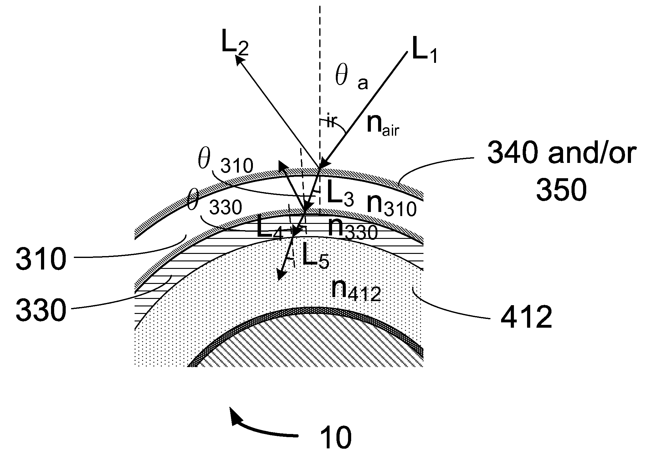
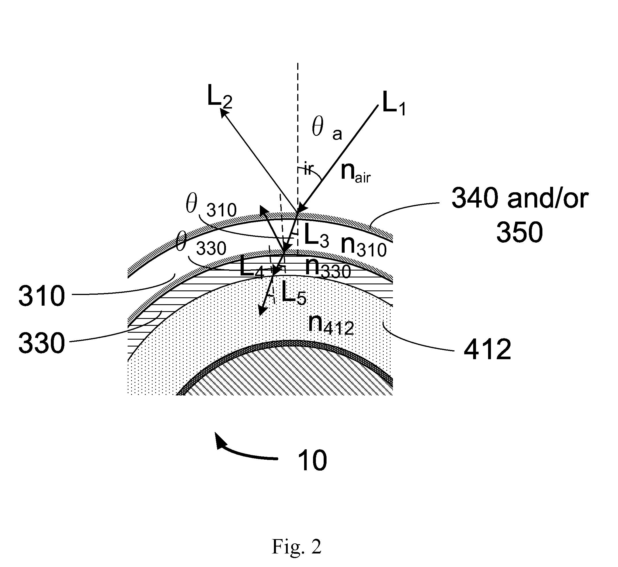
[0013]Systems and methods for maximizing the amount of light incident onto a solar cell or photovoltaic module, taking advantage of the effects of reflection and refraction, are provided. The transparent casing, filler material, and transparent conductive layer within a photovoltaic module each have indexes of refraction, and the values for the indexes are chosen so that light incident on the transparent casing is refracted towards the active layers of the solar cells of the photovoltaic module. The values of the refraction indexes are also chosen to reduce the amount of reflection that occurs at the surface boundary of the aforementioned layers.
[0015]In some embodiments, the second refractive index has a value approximately equal to the third refractive index plus X, where X is half the absolute difference between the values of the first and third refractive indexes. In some embodiments, the third refractive index is slightly more than the second refractive index. In some embodiments, the second refractive index is approximately equal to the first refractive index. In some embodiments, the second refractive index is approximately equal to the third refractive index. In some embodiments the first and second refractive indexes are chosen to minimize the reflection of light on the surface of the transparent conductive layer.
[0017]In some embodiments, the first, second, and third refractive indexes are chosen such that light incident on the transparent casing is refracted towards a solar cell within the photovoltaic module. In some embodiments, the one or more solar cells on a substrate within the transparent casing of the photovoltaic module each have a first surface area and the transparent casing has a second surface area. In such embodiments, the first, second, and third refractive indexes are chosen such that the one or more solar cells on the substrate within the transparent casing exhibit an effective optical surface area approximately equal to the second surface area. In some embodiments, the second and third refractive indexes are chosen to minimize the reflection of light on the surface of the filler material of the photovoltaic module.

Problems solved by technology

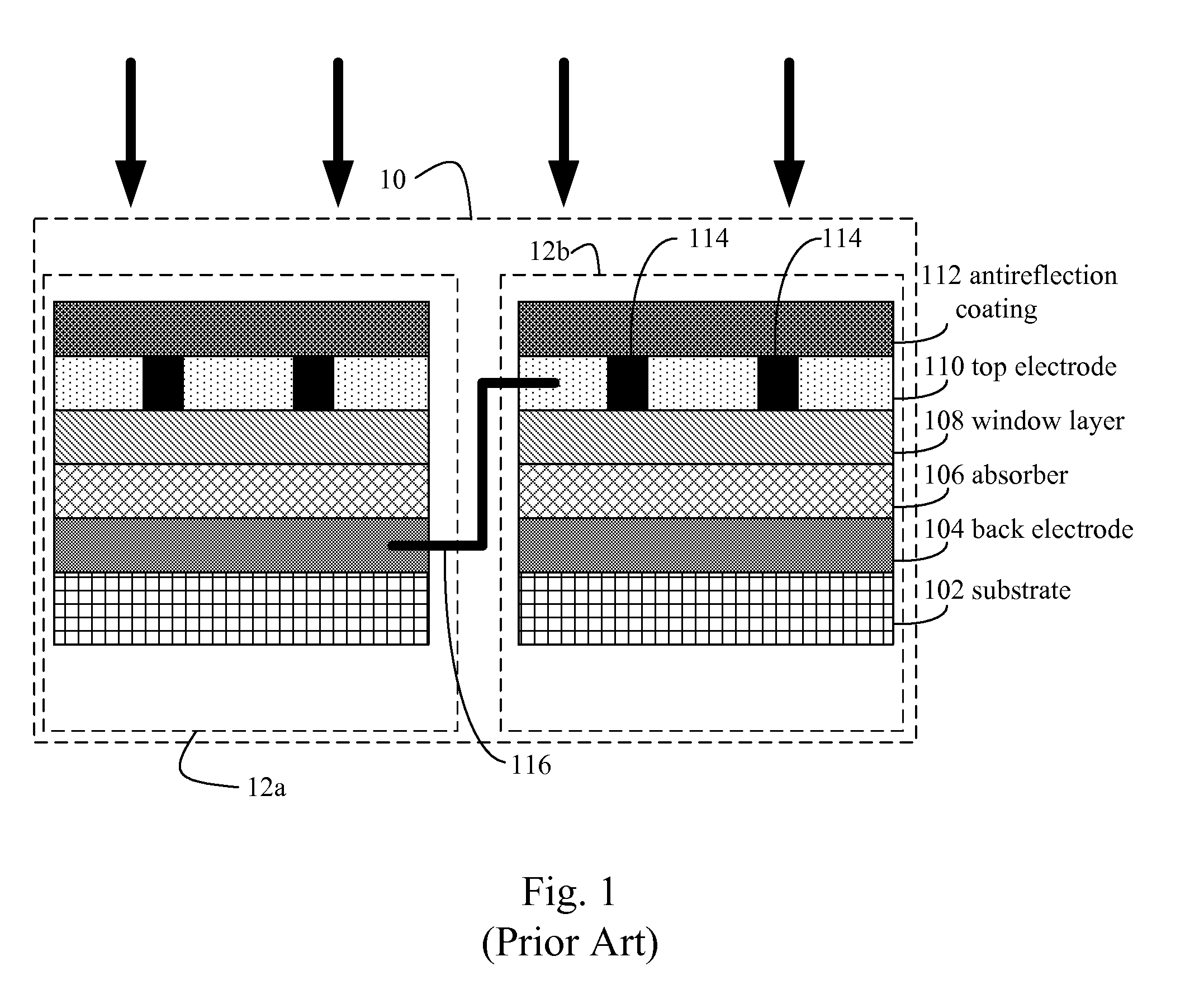
However, even when a TCO layer is present, a bus bar network 114 is typically needed in conventional photovoltaic modules 10 to draw off current since the TCO has too much resistance to efficiently perform this function in larger photovoltaic modules.
Furthermore, the occurrence of pinholes and similar flaws increase in larger planar solar cells 12.
These features can cause shunts across the junction.

Method used


Image

  • Photovoltaic Modules Having a Filling Material
  • Photovoltaic Modules Having a Filling Material
  • Photovoltaic Modules Having a Filling Material

Examples


Embodiment Construction

[0053]A photovoltaic module having an elongated substrate is provided. A portion of the elongated substrate is rigid. One or more solar cells are disposed on the elongated substrate. The one or more solar cells each comprise (i) a back-electrode disposed on the elongated substrate, (ii) a semiconductor junction layer disposed on the back-electrode, (iii) and a transparent conductive layer disposed on the semiconductor junction, where the transparent conductive layer has a first refractive index. A filler material is disposed on the transparent conductive layer. The filler material has a second refractive index that is smaller or equal in value to said first refractive index. A transparent casing is disposed on the filler material thereby sealing the photovoltaic module. In some embodiments, the transparent casing has a third refractive index that is smaller or equal in value to the second refractive index. In some embodiments, the transparent casing has a third refractive index that...


PUM


Abstract

A photovoltaic module comprising an elongated substrate in which at least a portion of the elongated substrate is rigid is provided. One or more solar cells are disposed on the elongated substrate and each comprise: (i) a back-electrode disposed on the elongated substrate, (ii) a semiconductor junction layer disposed on all or a portion of a surface of the back-electrode, and (iii) a transparent conductive layer, having a first refractive index, is disposed on all or a portion of a surface of the semiconductor junction. The photovoltaic module further comprises a filler material, having a second refractive index that is smaller or equal in value to the first refractive index, disposed on the transparent conductive layer of the one or more solar cells. The photovoltaic module further comprises a transparent casing disposed on the filler material thereby sealing the photovoltaic module.

Description

CROSS-REFERENCE TO RELATED APPLICATIONS[0001]This application is a continuation-in-part of U.S. patent application Ser. No. 11 / 800,089, entitled “Elongated Photovoltaic Cells in Casings,” filed on May 3, 2007 which, in turn, is a continuation-in-part of U.S. patent application Ser. No. 11 / 378,847 entitled “Elongated Photovoltaic Cells in Tubular Casings,” filed on Mar. 18, 2006, each of which is hereby incorporated by reference herein in its entirety. This application is also a continuation-in-part of U.S. patent application Ser. No. 12 / 039,659, entitled “A Photovoltaic Apparatus Having a Filler Layer and Method for Making the Same,” filed on Feb. 28, 2008 which, in turn, claims priority to U.S. Patent Application No. 60 / 906,901 entitled “A Photovoltaic Apparatus Having a Filler Layer and Method for Making the Same,” filed on Mar. 13, 2007, each of which is hereby incorporated by reference herein in its entirety. This application also claims priority to U.S. Patent Application No. 6...

Claims


Application Information

Patent Timeline
IPC IPC(8): H01L31/042
CPCH01L31/02168H01L31/022433Y02E10/52H01L31/042H01L31/048H01L31/035281H01L31/0504H01L31/055H01L31/046H01L31/0547H01L31/0463H01L31/0481
Inventor BECK, MARKUS E.CUMPSTON, BRIAN H.BULLER, BENYAMIN
Owner SOLYNDRA RESIDUAL TRUST
Learn More