
Vapor recovery system for a direct injector fuel rail assembly

a fuel rail and recovery system technology, applied in the direction of condensed fuel collection/return, fuel injection apparatus, charge feed system, etc., can solve the problem of not being able to contain all escaping fuel vapors with the current use of evaporative control system, and achieve the effect of avoiding secondary machining, reducing weight and manufacturing costs

Inactive Publication Date: 2009-01-15
DELPHI TECH INC
View PDF28 Cites 10 Cited by
  • Summary
  • Abstract
  • Description
  • Claims
  • Application Information

AI Technical Summary

Benefits of technology

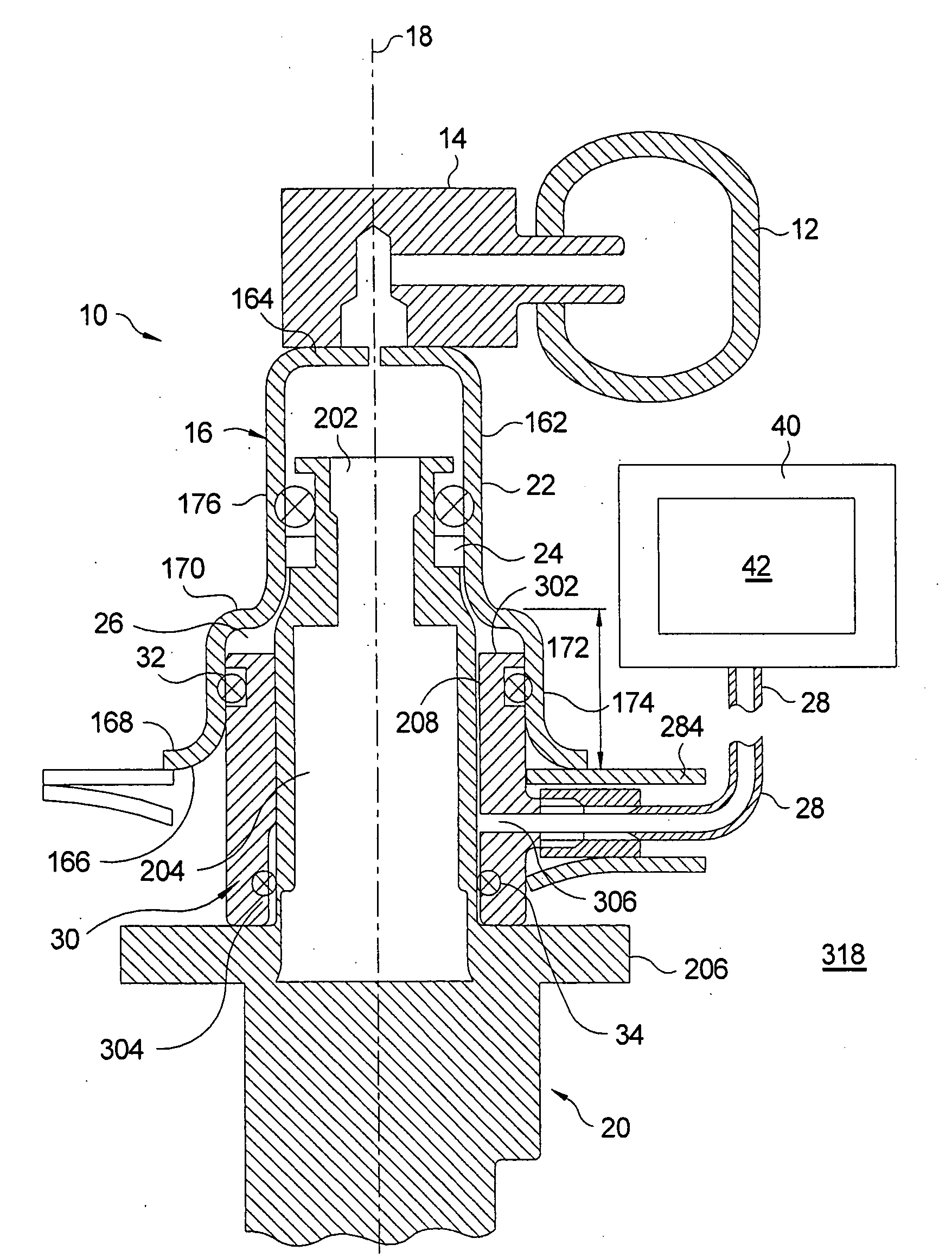
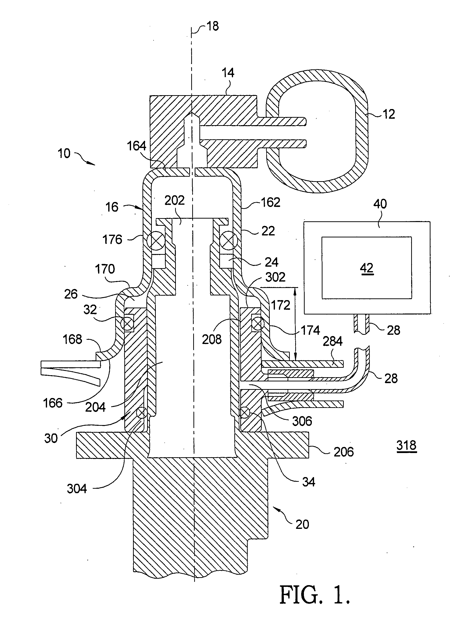
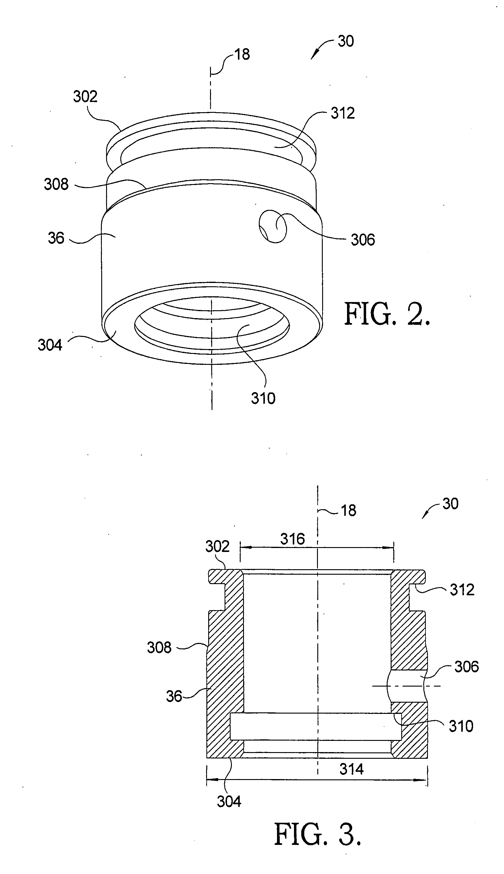
[0011]In accordance with the present invention, the collar is manufactured from a composite material to eliminate the need for secondary machining, and to keep the weight and the manufacturing costs low. The collar includes at least one groove for receiving an o-ring that assists forming the secondary sealed chamber around the injector. Furthermore, the collar includes an opening for receiving a vapor line. The vapor line connects the secondary sealed chamber with an evaporative emission canister of an evaporative control system. The fuel vapor captured in the secondary sealed chamber created by the collar is returned to the intake manifold for combustion and, therefore, not released to the environment. By integrating the collar into the fuel rail assembly in accordance with the invention current DIG internal combustion engines may be converted to PZEV DIG engines.

Problems solved by technology

Nevertheless, due to the high pressure in the fuel rail and the injector socket, fuel vapor may still escape past a primary injector seal.
However, it is currently not possible to contain all escaping fuel vapors with currently used evaporative control systems.

Method used


Image

  • Vapor recovery system for a direct injector fuel rail assembly
  • Vapor recovery system for a direct injector fuel rail assembly
  • Vapor recovery system for a direct injector fuel rail assembly

Examples


Embodiment Construction

[0017]Referring to FIG. 1, a DIG fuel rail assembly 10 with a fuel injector assembly 20 inserted is illustrated in accordance with the invention. The fuel rail assembly 10 includes, as its main components, fuel distribution tube 12, a socket block 14, a fuel injector socket 16, and a collar 30. A passage in socket block 14 connects the fuel injector socket 16 with the fuel distribution tube 12. A plurality of fuel injector sockets 16 may be connected to the distribution tube 12 in one aspect of the invention.

[0018]The fuel injector socket 16 includes a generally cylindrical elongated body 162 that extends longitudinally along central axis 18. The body 162 of the injector socket 16 has the shape of an extended stepped cup that is closed at a first end 164 and open at a second end 166. The first end 164 is in fluid communication with fuel distribution tube 12 via the passage in socket block 14. The second end 166 defines a flange 168. Body 162 further includes a step 170 at a distance...


PUM


Abstract

A fuel rail assembly for injection of fuel includes a fuel injector socket having a fuel injector assembly inserted, a collar surrounding said fuel injector assembly and providing a gap there between; and a seal sealing the gap between the collar and the fuel injector assembly thereby forming a secondary chamber. Fuel vapors that escape the primary seal of the fuel injector installed in the fuel injector socket are captured in the secondary sealed chamber and are directed to an evaporative control system. The collar is designed such that only minimum modifications are required to both current injectors and current injector sockets. By integrating the collar into a DIG fuel rail assembly in accordance with the invention current DIG internal combustion engines may be converted to PZEV DIG engines.

Description

TECHNICAL FIELD[0001]The present invention relates to engine management systems and components of internal combustion engines; more particularly, to fuel injection systems for direct injection of fuel; and most particularly, to a collar used in fuel rail assemblies for direct injection of fuel for the collection and control of fuel vapors.BACKGROUND OF THE INVENTION[0002]Fuel rails that are used to deliver fuel to individual fuel injectors on internal combustion engines are well known. A fuel rail assembly, also referred to herein simply as a fuel rail, is essentially an elongated tubular fuel manifold connected at an inlet end to a fuel supply system and having a plurality of ports for mating in any of various arrangements with a plurality of fuel injectors to be supplied. Typically, a fuel rail assembly includes a plurality of fuel injector sockets in communication with a manifold supply tube, the injectors being inserted into the sockets. Some fuel rails also incorporate an attac...

Claims


Application Information

Patent Timeline
Patent Type & Authority Applications(United States)
IPC IPC(8): F02M61/16
CPCF02M55/007F02M55/005
Inventor KEEGAN, KEVIN R.MEEKER, JARED I.CALOROSO, KIRK W.
Owner DELPHI TECH INC
Learn More