
Fuel production from atmospheric CO2 and H20 by artificial photosynthesis and method of operation thereof

a technology of atmospheric co2 and h20, which is applied in the direction of solid fuels, fuel and primary cells, petroleum industry, etc., can solve the problems that no one has provided the free selection of carbonaceous fuels to be produced efficiently and in a substantial capacity

Inactive Publication Date: 2009-01-15
YOUNG EDGAR D
View PDF4 Cites 8 Cited by
  • Summary
  • Abstract
  • Description
  • Claims
  • Application Information

AI Technical Summary

Benefits of technology

[0013]The present invention relates generally to reduction of atmospheric carbon dioxide and to fuel production, and more specifically, to carbonaceous fuel production by means of utilization of atmospheric CO2 and H20 by “artificial photosynthesis”, as defined herein and methods of operation thereof.

Problems solved by technology

Wherefore, these considerations may impose constraints upon the combustion chamber design under the corresponding embodiment hereof, as well as upon the separation process.
However, none have provided the free selection of carbonaceous fuels to be produced efficiently and in a substantial capacity.

Method used


Image

  • Fuel production from atmospheric CO2 and H20 by artificial photosynthesis and method of operation thereof
  • Fuel production from atmospheric CO2 and H20 by artificial photosynthesis and method of operation thereof
  • Fuel production from atmospheric CO2 and H20 by artificial photosynthesis and method of operation thereof

Examples


Embodiment Construction

[0020]In describing preferred embodiments of the present invention illustrated in the Figures, specific terminology may be employed for the sake of clarity. The present invention, however, is not intended to be limited to the specific terminology so selected, and it is to be understood that each specific element or step hereof includes all technological equivalents that operate in a similar manner to accomplish a similar purpose.

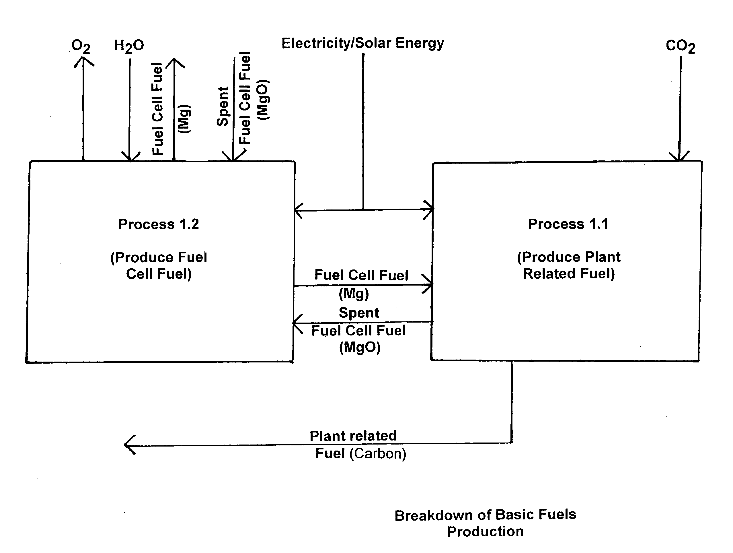
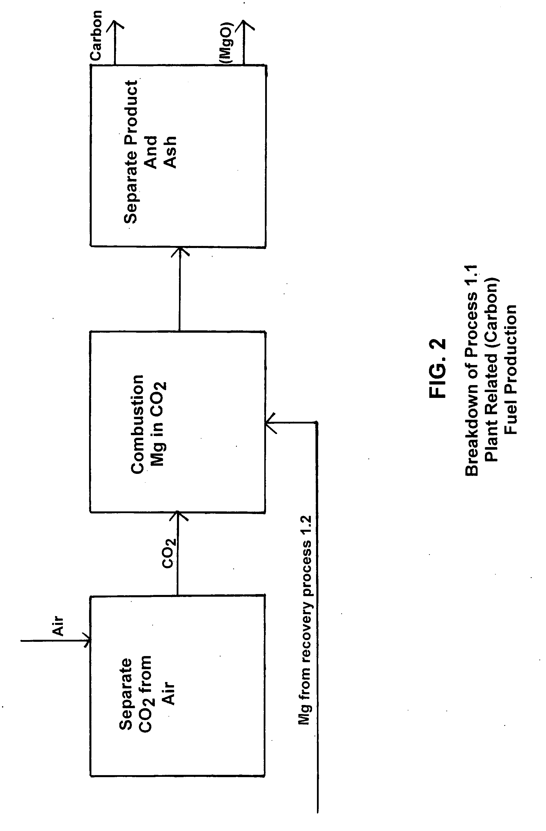
[0021]In one form of the preferred embodiment of the present invention as chosen for purposes of illustration, FIG. 1 shows a breakdown of the main process into sub-processes for producing carbon and for recovering magnesium, and further providing schematic details of Process 1.1, and in which the input therefrom comprises the use of CO2 and magnesium or other similar metal, and the output therefrom constitutes metallic oxide and plant related fuel in the form of carbon. The means used therein preferably comprise electricity, in the form of solar energy, win...


PUM

PropertyMeasurementUnit
temperatureaaaaaaaaaa
polarityaaaaaaaaaa
energyaaaaaaaaaa

Abstract

The present invention relates generally to reduction of atmospheric carbon dioxide and to fuel production, and more specifically, to carbonaceous fuel production by means of utilization of atmospheric carbon dioxide and water by “artificial photosynthesis”, as defined herein and methods of operation thereof.

Description

TECHNICAL FIELD[0001]The present invention relates generally to fuel production, and more specifically, to carbonaceous fuel production by means of utilization of atmospheric carbon dioxide and water by “artificial photosynthesis”, as defined herein, and methods of operation thereof.BACKGROUND OF THE INVENTION[0002]The current state of affairs regarding Carbon Dioxide and its close relationship to global warming has reached an all time high. Many responsible sources contend that the condition of the earth's atmosphere is such that, in order to avoid the predicted dire consequences of global warming affects, removal of a portion of the existing, and increased, carbon dioxide from the atmosphere (in a preferred amount approximating one billion tons annually for about a decade) is needed.[0003]The methods of the present invention meet these drastic requirements and also further provide a substantial environmental benefit in which the inventive processes hereof would require no addition...

Claims


Application Information

Patent Timeline
Patent Type & Authority Applications(United States)
IPC IPC(8): C10L8/00
CPCH01M12/06C10L8/00
Inventor YOUNG, EDGAR D.
Owner YOUNG EDGAR D
Learn More