Differential transmission line connector
a technology of transmission line and connector, which is applied in the direction of pulse conversion, coupling device connection, pulse technique, etc., can solve the problem of unwanted radiation noise that cannot be reduced, and achieve the effect of constant length of signal lines
- Summary
- Abstract
- Description
- Claims
- Application Information
AI Technical Summary
Benefits of technology
Problems solved by technology
Method used
Image
Examples
first embodiment
[0077]
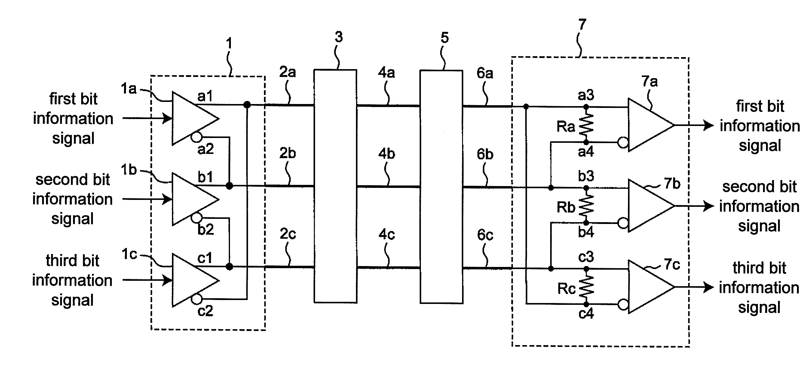
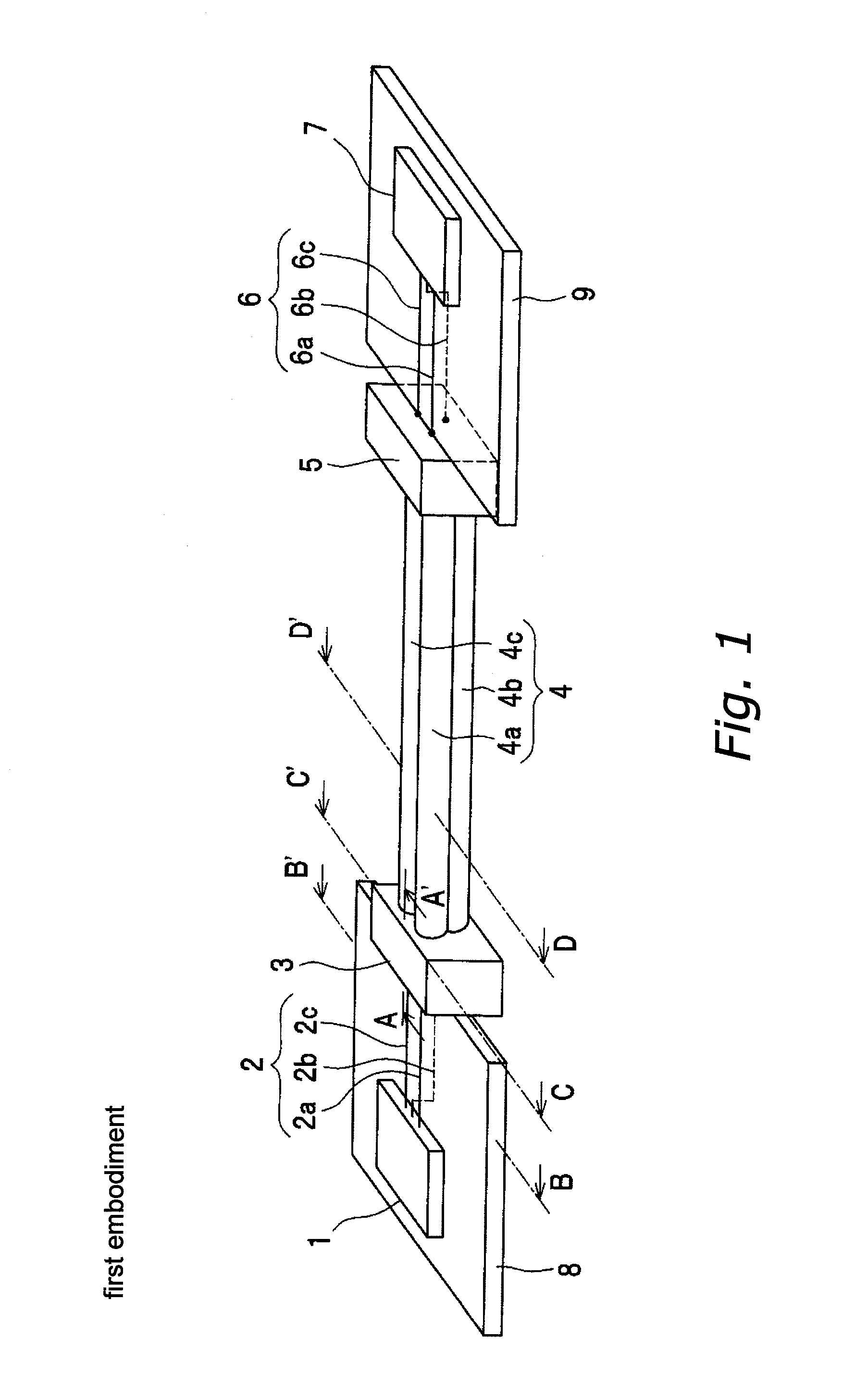
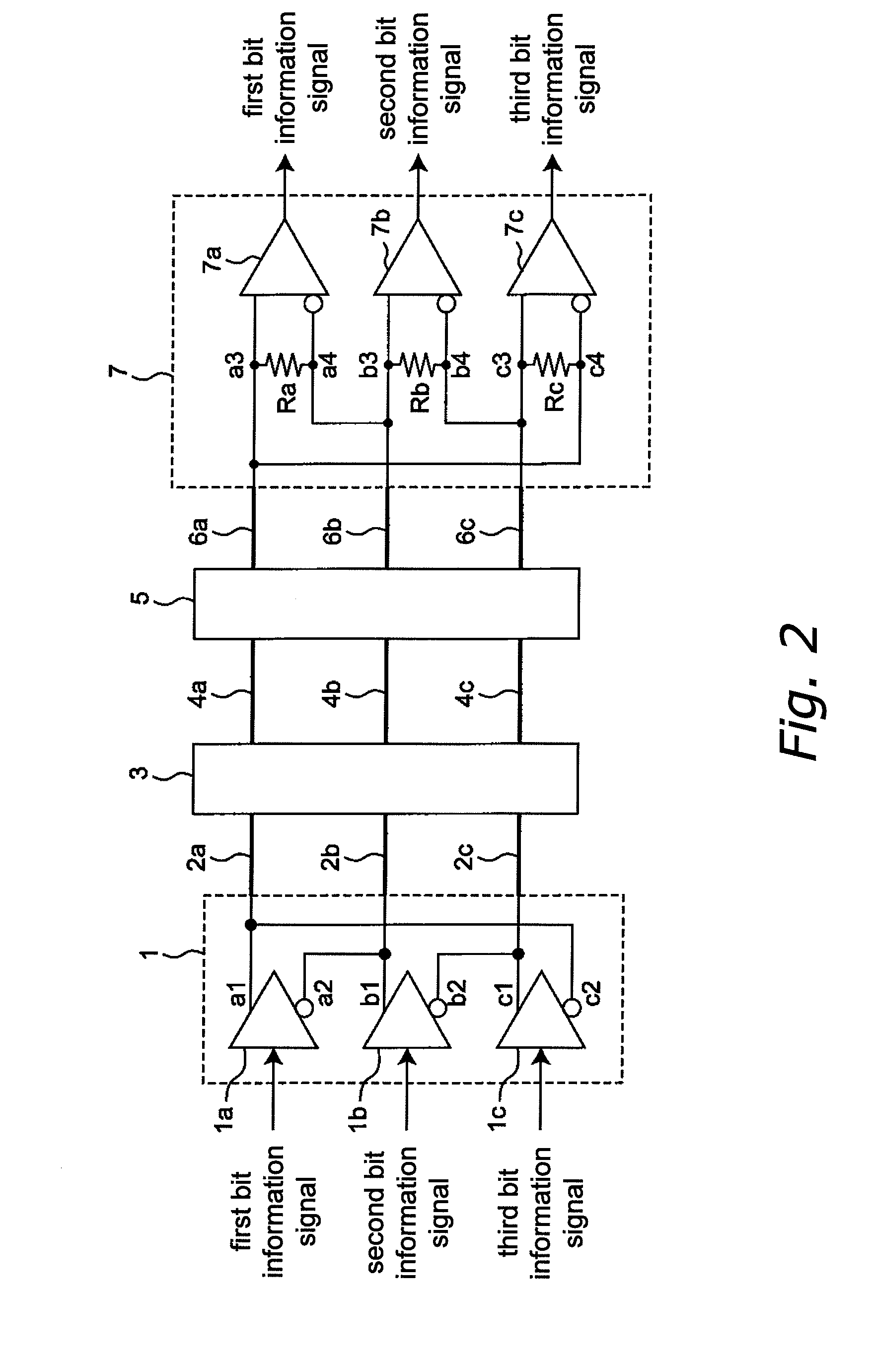
[0078]FIG. 1 is a perspective view showing the structure of a differential transmission system according to a first embodiment of the invention, and FIG. 2 is a circuit diagram of the differential transmission system of FIG. 1. With the differential transmission system of this embodiment, three bit information signals are differentially signaled simultaneously by LVDS (that is, multiple differential transmission is performed) via a differential transmission line that is made of three signal lines. In FIG. 1, the differential driver IC1, which is provided on a first printed circuit board 8, which is a double-sided board, and a differential receiver IC7, which is provided on a second printed circuit board 9, which is a double-sided board and which is different from the first printed circuit board 8, are connected to one another by a differential transmission line that is made from three signal lines. Here, the differential transmission line is made from a differential transmissi...
modified example
[0130]FIG. 29 is a flowchart that illustrates this example of the bit information determination process that is executed by the decoding device 50 of the signal receiver 7B in a multiple differential transmission system according to a modified example of the third multiple differential transmission system (using the configuration of FIG. 25, differing only in the setting conditions). Here, the structural configuration of the multiple differential transmission system of FIG. 25 is used. The bit information determination process of FIG. 29 differs from the bit information determination process of FIG. 26 only in that the processing of step S13 has been switched with the processing of step S14. This multiple differential transmission system according to a modified example of the third multiple differential transmission system with this configuration has the same actions and effects as the multiple differential transmission system according to the modified example of the second multiple...
second embodiment
[0140]FIG. 7 is a perspective view showing the configuration of a differential transmission system according to a second embodiment of the invention, FIG. 8 is a vertical cross section showing a cut section taken along line H-H′ in FIG. 7, and FIG. 9 is a front view showing the configuration of the connector 3A along the line I-I′ in FIG. 7. This embodiment is characterized in that connectors 3A and 5A that are provided on the upper surface of printed circuit boards 8A and 9A are provided in lieu of the connectors 3 and 5 that were provided on the end surfaces of the printed circuit boards 8 and 9 in the first embodiment.
[0141]The features of the differential transmission line connector 3A according to this embodiment are described below with reference to FIGS. 8 and 9. In this embodiment, the differential transmission pattern 2 of the printed circuit board 8A extends from the output terminals of the differential driver IC1 to a predetermined location on the printed circuit board 8A...
PUM
 Abstract
Description
Claims
Application Information
 - R&D
- Intellectual Property
- Life Sciences
- Materials
- Tech Scout
- Unparalleled Data Quality
- Higher Quality Content
- 60% Fewer Hallucinations
Browse by: Latest US Patents, China's latest patents, Technical Efficacy Thesaurus, Application Domain, Technology Topic, Popular Technical Reports.
© 2025 PatSnap. All rights reserved.Legal|Privacy policy|Modern Slavery Act Transparency Statement|Sitemap|About US| Contact US: help@patsnap.com


