
Liquid crystal display device and method for driving same

a liquid crystal display and display device technology, applied in the field of liquid crystal display, can solve the problems of flicker phenomenon, too slow response speed of liquid crystal molecules employed in such lcd devices,

Active Publication Date: 2009-01-01
INNOLUX CORP
View PDF5 Cites 1190 Cited by
  • Summary
  • Abstract
  • Description
  • Claims
  • Application Information

AI Technical Summary

Benefits of technology

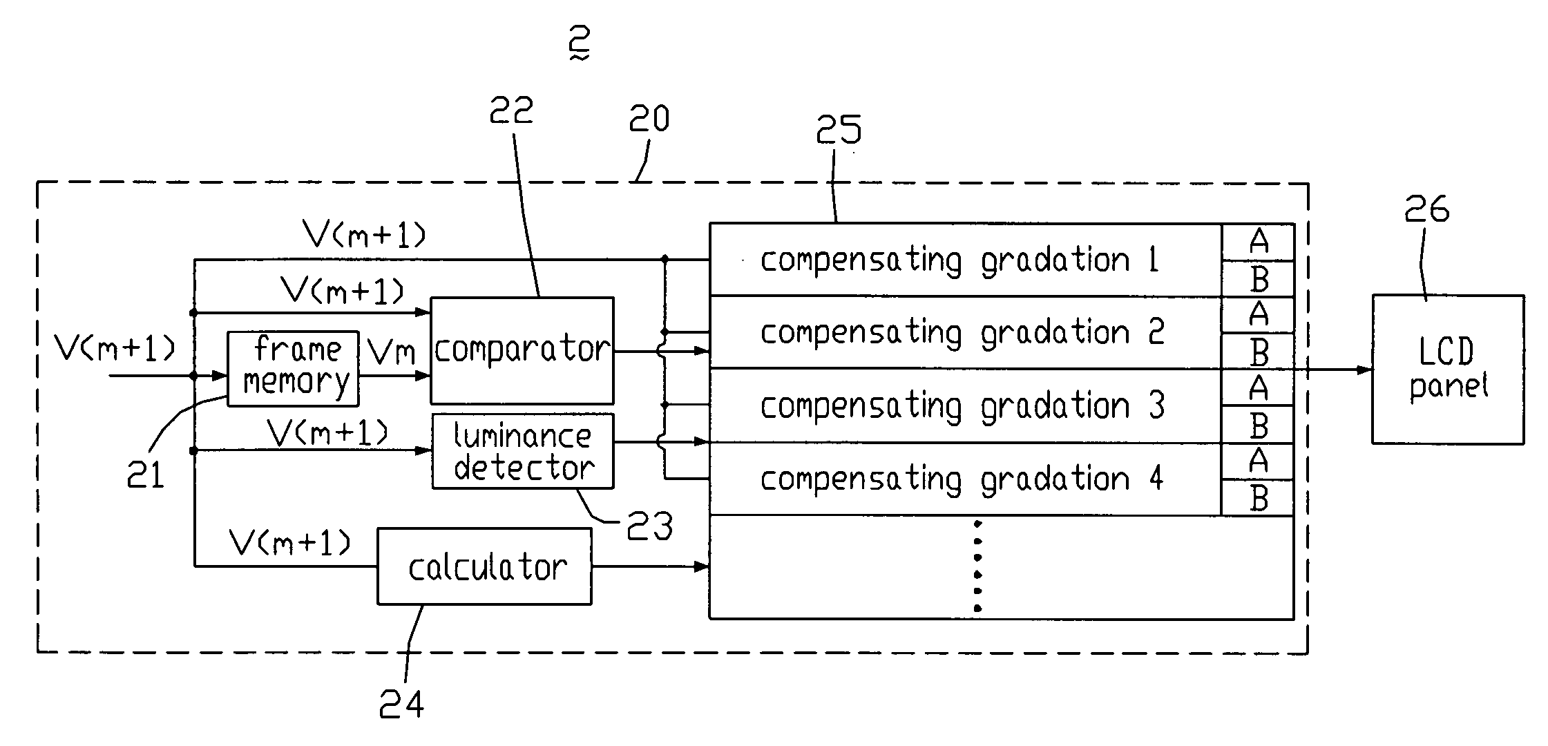
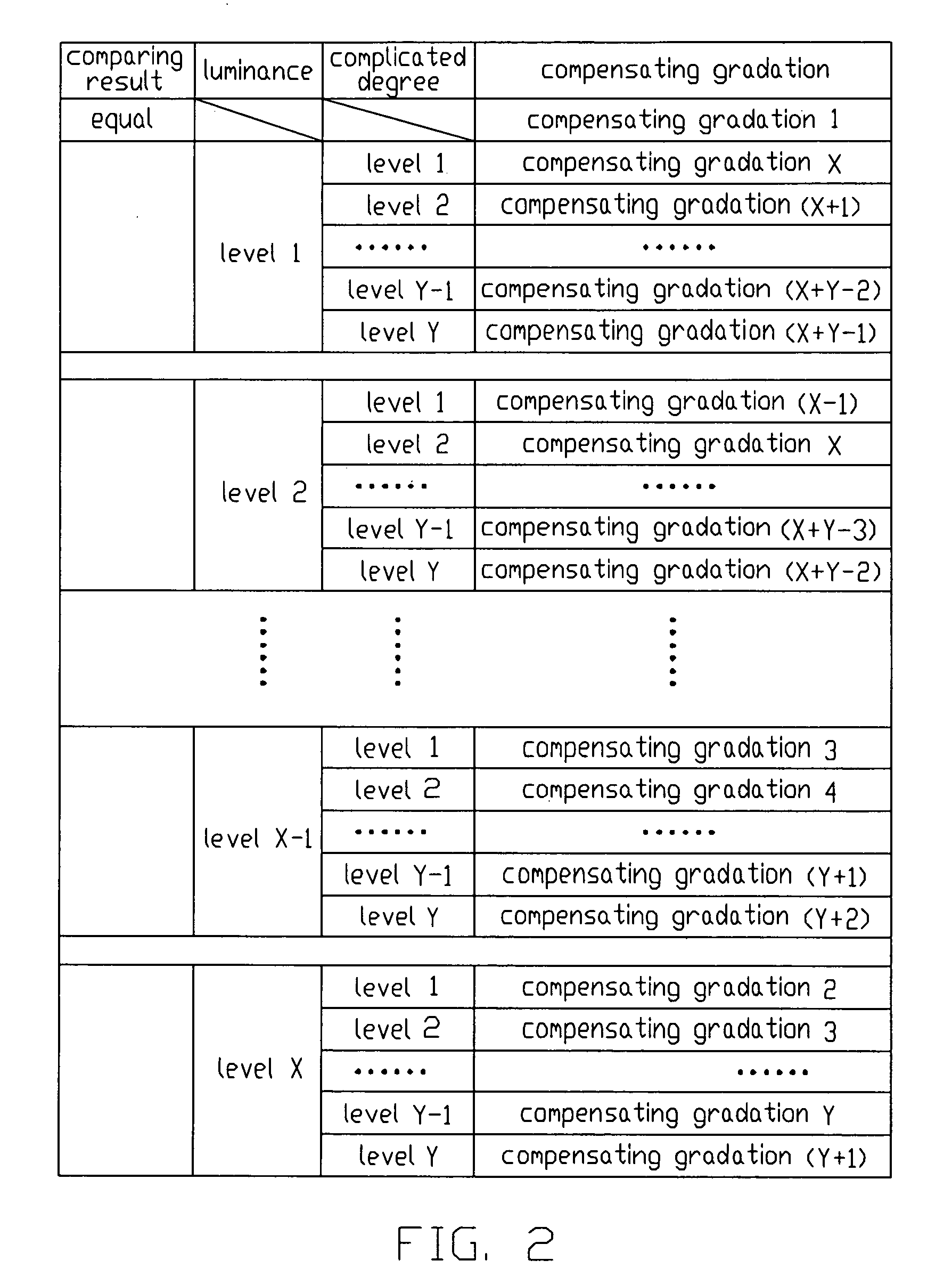
[0015]In one preferred embodiment, an LCD includes an LCD panel, the LCD includes a frame memory configured for receiving a plurality of first gradations of a current frame to be displayed and outputting a plurality of second gradations of a preceding frame pre-stored therein; a comparator configured for receiving the first gradations of the current frame and the second gradations of the preceding frame, and comparing the first gradations with the second gradations to generate a comparison result; a luminance detector configured for detecting a luminance degree of each of pixels of the LCD panel to be displayed in the current frame according to the gradations of the current frame; a calculator configured for calculating a degree of complication of a picture to be displayed in the current frame; and a gradation processor configured for receiving the first gradations of the current frame to be displayed on the LCD panel, generating a plurality of pairs of compensating gradations according to the first gradation of each pixel, and selecting one pair of the compensating gradations to be outputted to the LCD panel according to the comparison result, a received luminance degree, and the complication degree; wherein the calculator is further configured for providing the complication degree to the gradation processor.

Problems solved by technology

On the other hand, the display mode of typical LCD devices is hold-type, and the response speed of liquid crystal molecules employed in such LCD devices may be too slow.
However, because a black image is displayed between every two actual images, a viewer may easily perceive a flicker phenomenon.

Method used


Image

  • Liquid crystal display device and method for driving same
  • Liquid crystal display device and method for driving same
  • Liquid crystal display device and method for driving same

Examples


Embodiment Construction

[0022]Reference will now be made to the drawings to describe various embodiments of the present invention in detail.

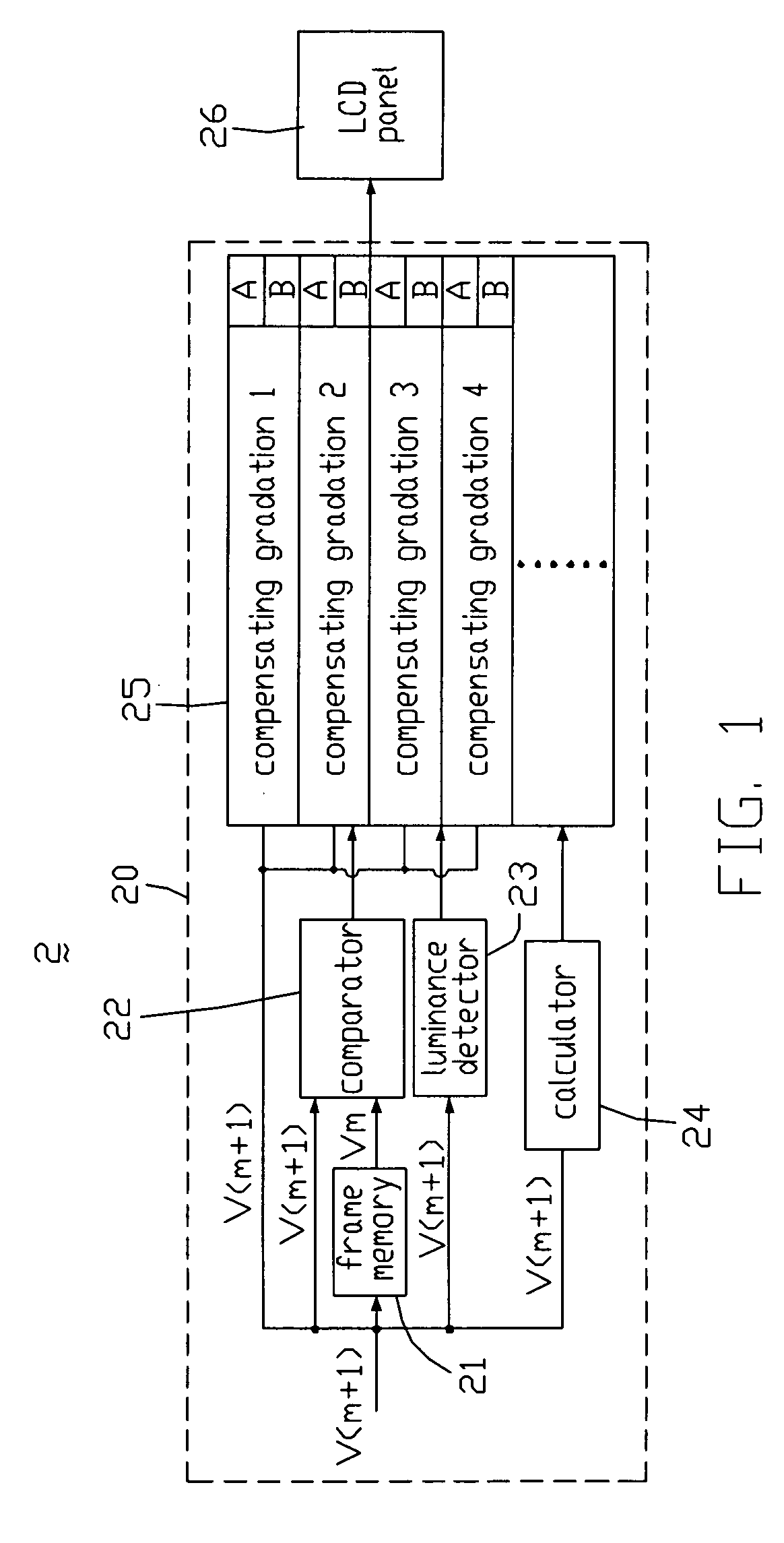
[0023]Referring to FIG. 1, an LCD 2 according to an exemplary embodiment of the present invention is shown. The LCD 2 includes an LCD panel 26 and a driving circuit 20 for driving the LCD panel 26. The driving circuit 20 includes a frame memory 21, a comparator 22, a luminance detector 23, a calculator 24, and a gradation processor 25. The LCD panel 26 includes a pixel matrix.

[0024]The frame memory 21 has a plurality of gradations V(m) of a number m (0≦m≦59, m is a natural number) frame pre-stored therein. The frame memory 21 receives a plurality of gradations V(m+1) of a number m+1 frame, and provides the gradations V(m) to the comparator 22.

[0025]The luminance detector 23 is configured for detecting a degree of luminance (hereinafter, “luminance degree”) of each pixel of the pixel matrix of the LCD panel 26 in the number m+1 frame.

[0026]It is assumed that the LCD pan...


PUM


Abstract

An exemplary LCD includes a frame memory configured for receiving a plurality of first gradations of current frame and outputting a plurality of second gradations of preceding frame pre-stored therein; a comparator configured for receiving, comparing the first gradations with the second gradation to generate a comparison result; a luminance detector configured for detecting a luminance degree of each of pixel according to the gradations of current frame; a calculator configured for calculating a complication degree of a picture to be displayed in current frame; and a gradation processor configured for receiving the first gradations of current frame to be displayed on the LCD panel, generating a plurality of pairs of compensating gradations according to the gradation of each pixel, and selecting one pair of the compensating gradations to be outputted to the LCD panel according to a received comparison result, a received luminance degree, and a received complication degree.

Description

FIELD OF THE INVENTION[0001]The present invention relates to a liquid crystal display (LCD) device configured to reduce image aberrations, and a method for driving such kind of LCD.GENERAL BACKGROUND[0002]Because typical LCD devices have the advantages of portability, low power consumption, and low radiation, they have been widely used in various portable information products such as notebooks, personal digital assistants (PDAs), video cameras, and the like. Furthermore, LCD devices are considered by many to have the potential to completely replace CRT (cathode ray tube) monitors and televisions. On the other hand, the display mode of typical LCD devices is hold-type, and the response speed of liquid crystal molecules employed in such LCD devices may be too slow. As a result, the residual image phenomenon may occur when motion pictures are displayed on LCD devices.[0003]In order to solve the above-described problems, a typical method employed for eliminating the residual image of LC...

Claims


Application Information

Patent Timeline
Patent Type & Authority Applications(United States)
IPC IPC(8): G09G5/02
CPCG09G3/2022G09G3/2081G09G3/3648G09G2360/16G09G2320/0252G09G2320/0261G09G2340/16G09G2320/0247
Inventor CHEN, EDDY GIING-LIICHEN, SZ-HSIAO
Owner INNOLUX CORP
Learn More