
Electric machine and method for determining the axial position of bearings for a rotor of the machine

a technology of electric machines and bearings, which is applied in the direction of mechanical energy handling, magnetic circuit rotating parts, magnetic circuit shape/form/construction, etc., can solve the problems of raising undesired thermal load, direct mounting with a conventional bearing is therefore impossible, etc., to and reduce the maximum deflection of the cooling tube

Active Publication Date: 2009-01-01
SIEMENS ENERGY GLOBAL GMBH & CO KG
View PDF1 Cites 1 Cited by
  • Summary
  • Abstract
  • Description
  • Claims
  • Application Information

AI Technical Summary

Benefits of technology

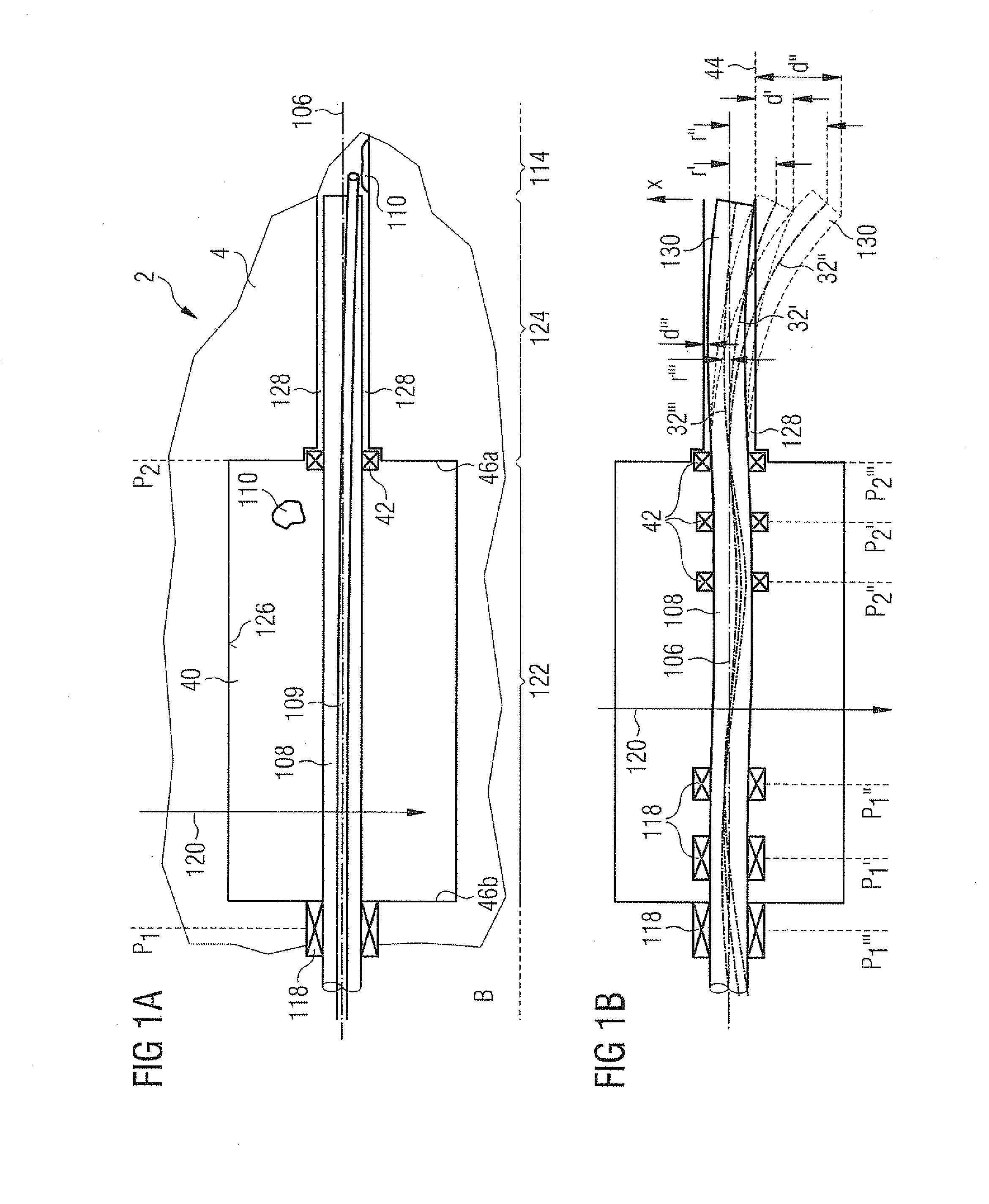
[0018]The bearings thereby form a device for the reduction of the maximum deflection of the cooling tube and are located in the first longitudinal section, so at the ambient air temperature, because of which inexpensive, conventional bearings can be used. By multiple mounting in the first longitudinal section to corresponding suitable axial positions, the deflection line of the inlet pipe upon action of the radial force on it is also influenced in the second longitudinal section, due to its inherent stability. By introduction of the minimum two cooling tube (or inlet pipe) bearing points, possibly even several bearing points, wherein two bearings in total are preferred, it is possible to form the deflection line of the cooling tube caused by gravity or shock load, i.e. acting in the radial direction, in such a way that in the critical area, i.e. in the area of the length of the cooling tube hanging free, the maximum deflection is substantially reduced in comparison with the original, simple mounting known in the prior art.
[0020]In electric machines with cooling tube dimensions typically used there, a clearly increased shock resistance for the electric machines can be directly achieved in this way, i.e. by introducing additional bearing points without further measures like constructive alteration of the inlet pipe, rotor or radial gap.

Problems solved by technology

However, both measures raise the undesired thermal load introduced into the area cooled to a cryogenic temperature.
A mounting of the free end of the cooling tube in the rotor would also be possible in principle, however this end is at a cryogenically low (rotor) temperature and conventional mounting in this location is rejected.
An inexpensive, direct mounting with a conventional bearing is therefore not possible.

Method used


Image

  • Electric machine and method for determining the axial position of bearings for a rotor of the machine
  • Electric machine and method for determining the axial position of bearings for a rotor of the machine
  • Electric machine and method for determining the axial position of bearings for a rotor of the machine

Examples


Embodiment Construction

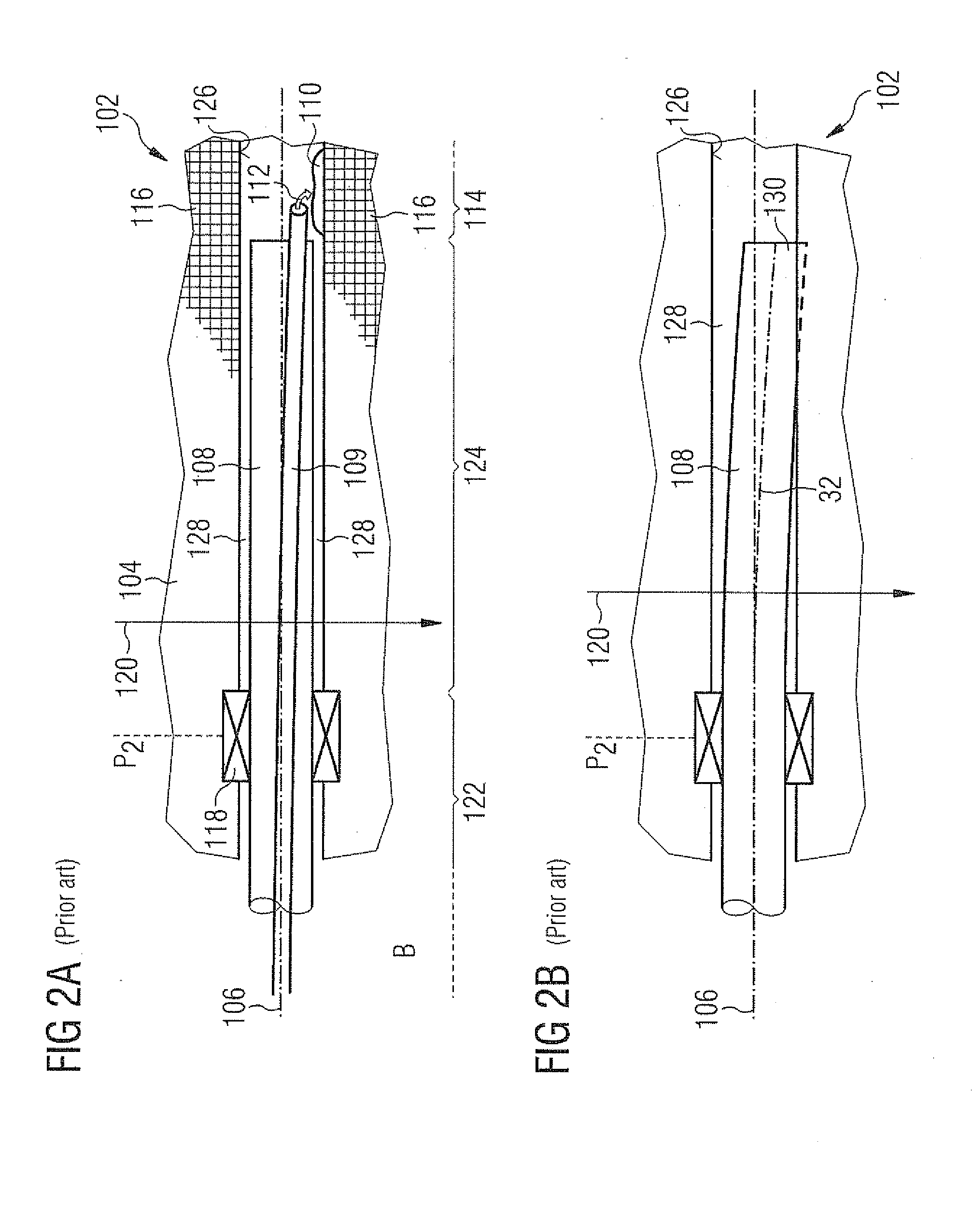
[0033]FIG. 1a shows a machine 2 according to the invention, of which a larger section on the B-side B is shown than in FIG. 2a,b. In comparison to FIGS. 2a,b, in FIG. 1a the rotor 4 is hollowed out in the section 122, or rather its interior diameter is extended, in order to form a cavity 40. The cavity 40 serves in the storage of working gas, gaseous neon 110, when the machine 2 is idle, if the whole machine 2 is heated to the surrounding air temperature. A corresponding cavity 40 is described in detail in the non-pre-published DE patent application 2007P05926 DE (date of application: Jun. 29, 2007) with the title “Electric machine with superconducting rotor winding”. In comparison to FIGS. 2a,b, the gastight rotary joint 118 is shifted in the direction of the B-side B onto the axial position P1. On their original position according to FIGS. 2a,b, namely the axial position P2, the cooling tube 108 is replaced by a gas-permeable bearing 42. Rotary joint 118 and bearing 42 are therefo...


PUM

PropertyMeasurementUnit
temperatureaaaaaaaaaa
cryogenic temperatureaaaaaaaaaa
radial forceaaaaaaaaaa

Abstract

An electric machine contains a rotor which contains a first longitudinal section at the ambient air temperature and a second longitudinal section cooled at least partially to cryogenic temperature, a coolant inlet pipe extending into the second longitudinal section, wherein the inlet pipe is set at a distance from the rotor by a radial gap, wherein the inlet pipe in the first longitudinal section is mounted by at least two bearings, wherein the bearings are distributed on axial positions in such a way that upon action of a maximum radial force on the inlet pipe the pipe has a maximum deflection which is smaller than the radial gap. In a method for determining the axial positions, various batches of potential locations are chosen for the axial positions of the bearings, according to potential locations which has a minimum gap greater than zero.

Description

CROSS REFERENCE TO RELATED APPLICATIONS[0001]This application claims the benefits of German application No. 10 2007 030 411.2 filed Jun. 29, 2007 and is incorporated by reference herein in its entirety.FIELD OF INVENTION[0002]The invention concerns an electric machine with a rotor with superconducting rotor winding, and a method for determining the axial position of at least two bearings for the rotor in the electric machine.BACKGROUND OF THE INVENTION[0003]Electric machines, in particular those with high power, can be equipped with superconducting rotor windings today. These kinds of synchronous machines require a cooling system in order to cool the rotor winding down to the operating temperature. A conventional specification of these kinds of cooling systems uses a so-called cooling tube in order to transfer liquid coolant from a thermosiphon system to the rotating machine and to return the evaporated coolant to the condenser. The end of a cooling tube like this, at room temperatu...

Claims


Application Information

Patent Timeline
Patent Type & Authority Applications(United States)
IPC IPC(8): H02K9/24
CPCH02K9/193Y10T29/49004Y02E40/625H02K55/04Y02E40/60
Inventor FRANK, MICHAELVAN HABELT, PETER
Owner SIEMENS ENERGY GLOBAL GMBH & CO KG
Learn More