
Energy recovery system

a technology of energy recovery and energy storage, applied in the direction of fluid couplings, servomotors, couplings, etc., can solve the problems of waste of energy, loss or waste of energy, and undesired heating of hydraulic fluid,

Inactive Publication Date: 2009-01-01
CATERPILLAR INC
View PDF15 Cites 125 Cited by
  • Summary
  • Abstract
  • Description
  • Claims
  • Application Information

AI Technical Summary

Problems solved by technology

One problem associated with this type of hydraulic arrangement involves efficiency.
As a result, the higher pressure fluid draining into the sump still contains some energy that is wasted upon entering the low pressure sump.
This wasted energy reduces the efficiency of the hydraulic system In addition, the fluid emptying to the low pressure reservoir is passed through a throttle valve to control a lowering or retracting speed of the actuator.
Throttling the fluid also results in a loss or waste of energy and undesired heating of the hydraulic fluid.
Although the system of the '769 patent may recover some hydraulic energy when operating under an overrunning load, it may require large components and a greater number of components that may increase the size, complexity, and cost of the system Because all of the fluid from the head end of the cylinder is discharged to the accumulator, the large size of the required accumulator may make packaging of the system difficult.
Also, when the cylinder is retracted quickly under the force of gravity, a large quantity of fluid may be rapidly discharged from the cylinder, and the second pump / motor may need to be large to accommodate the rapid flow and large volume of fluid.
The '769 patent system also requires an excessive number of hydraulic pumps, which may reduce the efficiency of the system and increase the control complexity and cost of the system

Method used


Image

  • Energy recovery system
  • Energy recovery system
  • Energy recovery system

Examples


Embodiment Construction

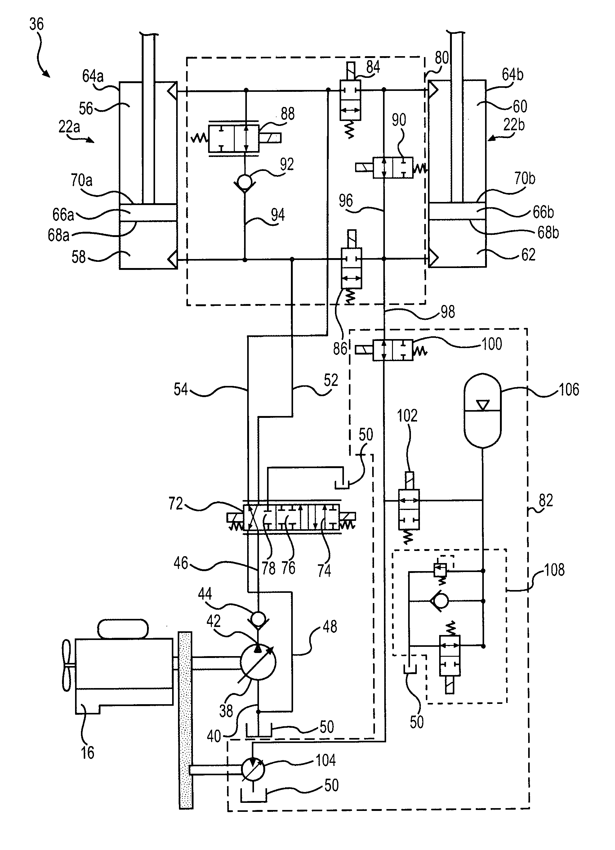
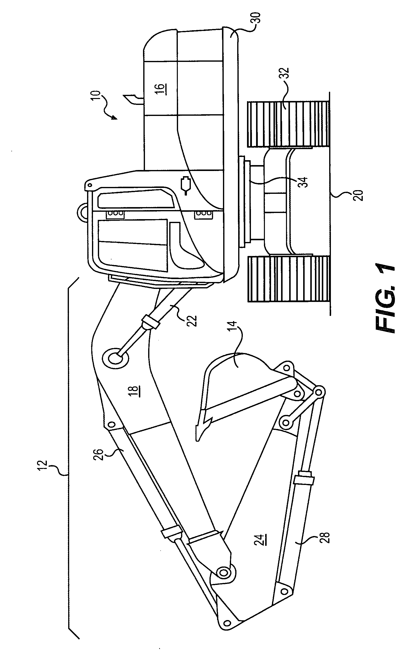
[0013]FIG. 1 illustrates an exemplary machine 10 having multiple systems and components that cooperate to accomplish a task. Machine 10 may embody a fixed or mobile machine that performs some type of operation associated with an industry such as mining, construction, farming, transportation, or any other industry known in the art. For example, machine 10 may be an earth moving machine such as the excavator depicted in FIG. 1. Alternatively, machine 10 may be a dozer, a loader, a backhoe, a motor grader, a haul truck, or any other earth-moving or task-performing machine. Machine 10 may include an implement system 12 configured to move a work tool 14, and a power source 16 that drives implement system 12.

[0014]Implement system 12 may include a linkage structure moved by fluid actuators to position and operate work tool 14. Specifically, implement system 12 may include a boom member 18 that is vertically pivotal about an axis relative to a work surface 20 by a pair of adjacent, double-...


PUM


Abstract

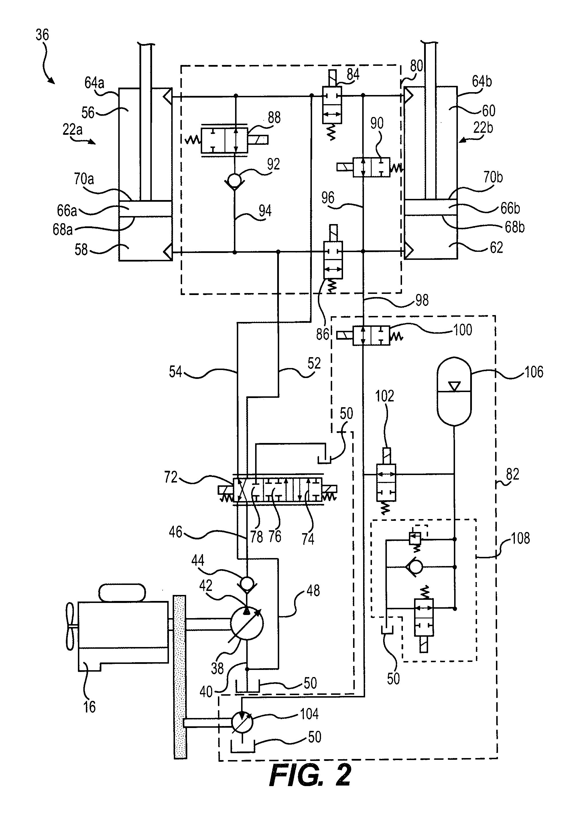
An energy recovery system for a machine is disclosed. The energy recovery system may have a pump configured to provide a flow of pressurized fluid. The energy recovery system may also have a first fluid actuator with a first chamber and a second chamber and being configured to receive the pressurized fluid, a second fluid actuator with a third chamber and a fourth chamber and being configured to receive the pressurized fluid, and a first valve fluidly connected between the pump and the first and second actuators. The energy recovery system may additionally include an isolation unit with a first selectively restrictable passageway fluidly connecting the first chamber, the third chamber, and a first outlet of the first valve, and a second selectively restrictable passageway fluidly connecting the second chamber, the fourth chamber, and a second outlet of the first valve, as well as an energy recovery unit in fluid communication with the isolation unit. The isolation unit may be configured to direct a flow of pressurized fluid from the second actuator to the energy recovery unit. The energy recovery unit may be configured to convert the flow of pressurized fluid to a first mechanical power output.

Description

TECHNICAL FIELD[0001]The present disclosure relates generally to an energy recovery system and, more particularly, to a system and method for accumulating and using recovered hydraulic energy.BACKGROUND[0002]Construction machines such as, for example, dozers, loaders, excavators, motor graders, and other types of heavy machinery use one or more hydraulic actuators to accomplish a variety of tasks. These actuators are fluidly connected to a pump on the construction machine that provides pressurized fluid to chambers within the actuators. As the pressurized fluid moves into or through the chambers, the pressure of the fluid acts on hydraulic surfaces of the chambers to effect movement of the actuator and a connected work tool. When the pressurized fluid is drained from the chambers it is returned to a low pressure sump on the construction machine.[0003]One problem associated with this type of hydraulic arrangement involves efficiency. In particular, the fluid draining from the actuato...

Claims


Application Information

Patent Timeline
Patent Type & Authority Applications(United States)
IPC IPC(8): F16D31/02
CPCE02F9/2075E02F9/2217E02F9/2296F15B11/024F15B21/14F15B2211/88F15B2211/20546F15B2211/3144F15B2211/625F15B2211/7053F15B2211/7128F15B2211/20523
Inventor BRINKMAN, JASON L.
Owner CATERPILLAR INC
Learn More