
Navigation aid

a monocular digital camera and navigation aid technology, applied in the field of navigation, can solve the problems of satellite signals unfit for position calculation, gps satellites may become unavailable to the gps receiver, and current global positioning system (gps) based navigation systems are inherently limited

Inactive Publication Date: 2008-12-25
TIDEX SYST
View PDF18 Cites 60 Cited by
  • Summary
  • Abstract
  • Description
  • Claims
  • Application Information

AI Technical Summary

Benefits of technology

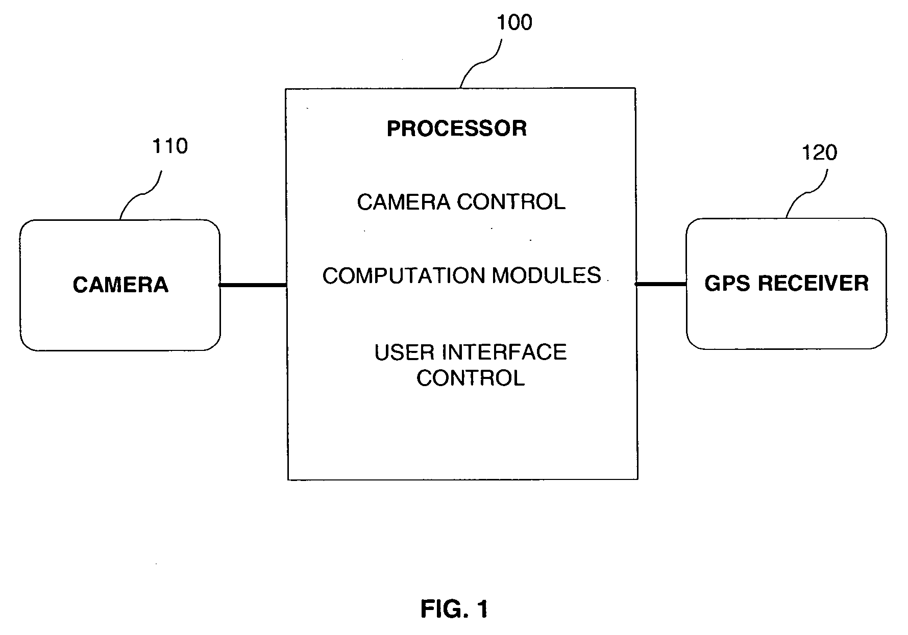
[0007]According to a first aspect of the present invention, there is provided a navigation aid comprising: a processor comprising camera control, computation modules and a user interface control; a digital camera connec...

Problems solved by technology

Current global positioning system (GPS) based navigation systems are inherently limited in that the global position determined is actually the position of the associated receiver.
The GPS satellites may become unavailable to the GPS receiver for various periods of time in, for example, urban environments, when the GPS receiver travels under a bridge, through a tunnel, or through what is referred to in the literature as an “urban canyon,” in which buildings block the signals or produce excessively large multipath signals that make the satellite signals unfit for position calculations.
In addition, operating the GPS receiver while passing through natural canyons and / or areas in which satellite coverage is sparse, may similarly result in the receiver being unable to track a sufficient number of satellites.
Thus, in certain environments the navigation information may be available only sporadically, and GPS-based navigation systems may not be appropriate for use as a navigation tool.
GPS signals may also be jammed or spoofed by hostile entities, and rendered useless as navigation aids.
The inertial system has well known problems, such as the derivation of the initial system (position, velocity and attitude) errors as well as IMU sensor errors that tend to introduce drifts into the inertial position information over time.

Method used


Image

  • Navigation aid
  • Navigation aid
  • Navigation aid

Examples


first embodiment

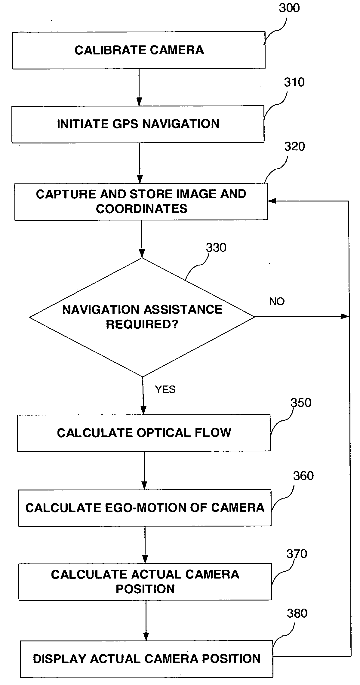
[0035]FIG. 3 is a flowchart describing the various steps involved in implementing the process of the present invention according to a

[0036]Step 300 is a preparatory step of calibrating the camera and lens. The calibration process measures camera and lens parameters such as focal length, lens astigmatism and other irregularities of the camera. These measurements are later used to correct the optical sensor's readouts. The calibration may be done using any method known in the art for calibrating digital camera lens distortions. According to one embodiment, the camera calibration uses the Flexible Camera Calibration Technique, as published in:[0037]Z. Zhang. A flexible new technique for camera calibration. IEEE Transactions on Pattern Analysis and Machine Intelligence, 22(11):1330-1334, 2000.[0038]Z. Zhang. Flexible Camera Calibration By Viewing a Plane From Unknown Orientations. International Conference on Computer Vision (ICCV'99), Corfu, Greece, pages 666-673, September 1999.

Both pu...

second embodiment

[0058]According to the present invention, the navigation aid may be used continuously and may serve as an additional means for accurate positioning along with a working global or local positioning device, preferably using the Kalman Filter algorithm for integrating the two data streams.

[0059]FIG. 4 is a flowchart describing the various steps involved in implementing the process of the present invention according to the second embodiment.

[0060]Steps 400 and 410 are similar to steps 300 and 310 of FIG. 3.

[0061]In step 420, two images are captured by the camera, optionally corrected with reference to the calibration step 400 and stored in buffer 240 along with their respective time-stamps. According to this second embodiment, the size of buffer 240 should only be sufficient for storing two captured images, as will be apparent from the explanation below.

[0062]In step 440, the optical flow is calculated in any of the methods described above in conjunction with FIG. 3. In this second embo...

third embodiment

[0065]According to the present invention, the navigation aid may function independent of any other global or local positioning device, for example as an orientation aid in a mine.

[0066]FIG. 5 is a flowchart describing the various steps involved in implementing the process of the present invention according to the third embodiment.

[0067]The steps are similar to those discussed in conjunction with FIG. 4, except that no GPS is required. Instead, initial reference coordinates, global or local, are set in step 510, to serve as reference for the subsequent relative positions calculated by the navigation aid.


PUM


Abstract

A method and apparatus for calculating exact positioning using a digital camera and a GPS, comprising calibrating the camera; initiating GPS navigation; capturing and storing images and GPS coordinates; calculating ego-motion of the camera using a pre-defined number of stored images; and calculating current position of the camera using the last stored GPS coordinates and the calculated camera ego-motion.

Description

FIELD OF THE INVENTION[0001]The current invention is in the field of navigation and more specifically, navigation assistance using a monocular digital camera.BACKGROUND OF THE PRESENT INVENTION[0002]Current global positioning system (GPS) based navigation systems are inherently limited in that the global position determined is actually the position of the associated receiver. The mounting location for the receiver must allow for a clear view of the GPS orbiting overhead. The GPS satellites may become unavailable to the GPS receiver for various periods of time in, for example, urban environments, when the GPS receiver travels under a bridge, through a tunnel, or through what is referred to in the literature as an “urban canyon,” in which buildings block the signals or produce excessively large multipath signals that make the satellite signals unfit for position calculations. In addition, operating the GPS receiver while passing through natural canyons and / or areas in which satellite ...

Claims


Application Information

Patent Timeline
IPC IPC(8): G01C21/00G06K9/00G06V10/147G06V10/24
CPCG01C21/005G06K9/209G06K9/32G06V10/147G06V10/24
Inventor KREMIN, ITZHAKBANITT, SHMUEL
Owner TIDEX SYST
Learn More