
Methods and apparatuses for power control

a power control and power technology, applied in the field of power control methods and apparatuses, can solve the problems of fluctuation in transmission from the ue, non-optimal use of resources within the wireless communication system, etc., and achieve the effect of facilitating a more dynamic signaling

Inactive Publication Date: 2008-12-25
QUALCOMM INC
View PDF16 Cites 137 Cited by
  • Summary
  • Abstract
  • Description
  • Claims
  • Application Information

AI Technical Summary

Benefits of technology

[0010]In another aspect, the resources assigned to the UEs for their uplink communications can be indexed. The power control messages transmitted to the UEs can comprise the indexing information in addition to the power control commands. This facilitates grouping UEs based at least on their radio conditions so that a group power control message can be transmitted to UEs having similar radio conditions. This facilitates dynamic signaling wherein only those UEs that require power correction receive power control commands while no resources are wasted in sending redundant communications to UEs already transmitting at optimum power levels.
[0013]The apparatus also facilitates a more dynamic signaling wherein the resources utilized by the UEs are indexed and the power control messages can comprise indexing information associated with the resources along with the power control commands. This facilitates grouping UEs based at least on their respective radio conditions and transmitting a common group power control messages to only those UEs requiring power corrections.

Problems solved by technology

However, various factors such as power constraints, signal attenuation, obstacles, etc. can lead to fluctuations in transmission from the UE.
However, the resources assigned for transmitting power control commands are assigned statically so that even if a UE is not transmitting or transmitting at optimum power levels, resources for power control commands, remain assigned thereby leading to a non-optimal use of resources within the wireless communication system.

Method used


Image

  • Methods and apparatuses for power control
  • Methods and apparatuses for power control
  • Methods and apparatuses for power control

Examples


Embodiment Construction

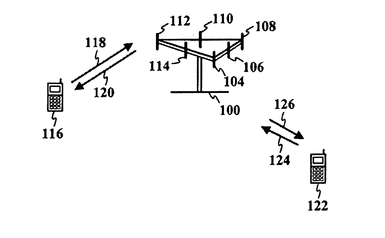
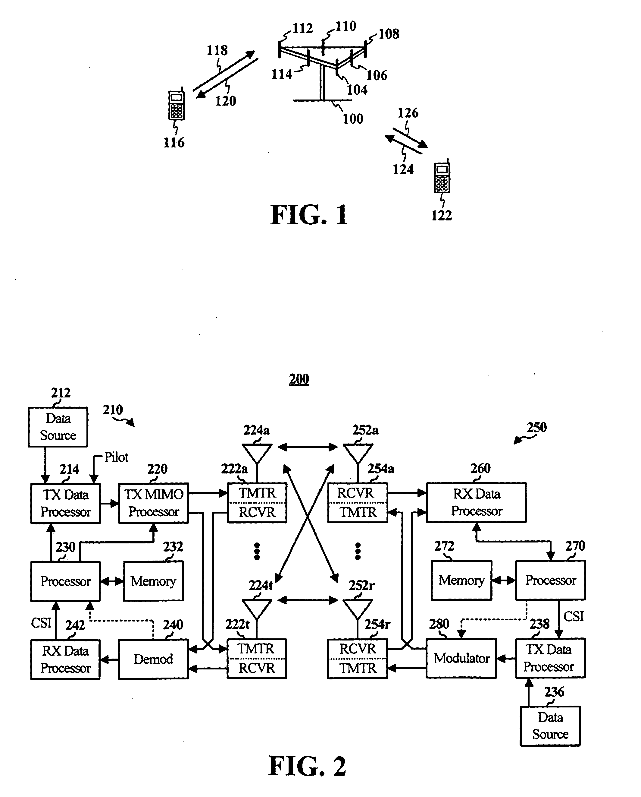
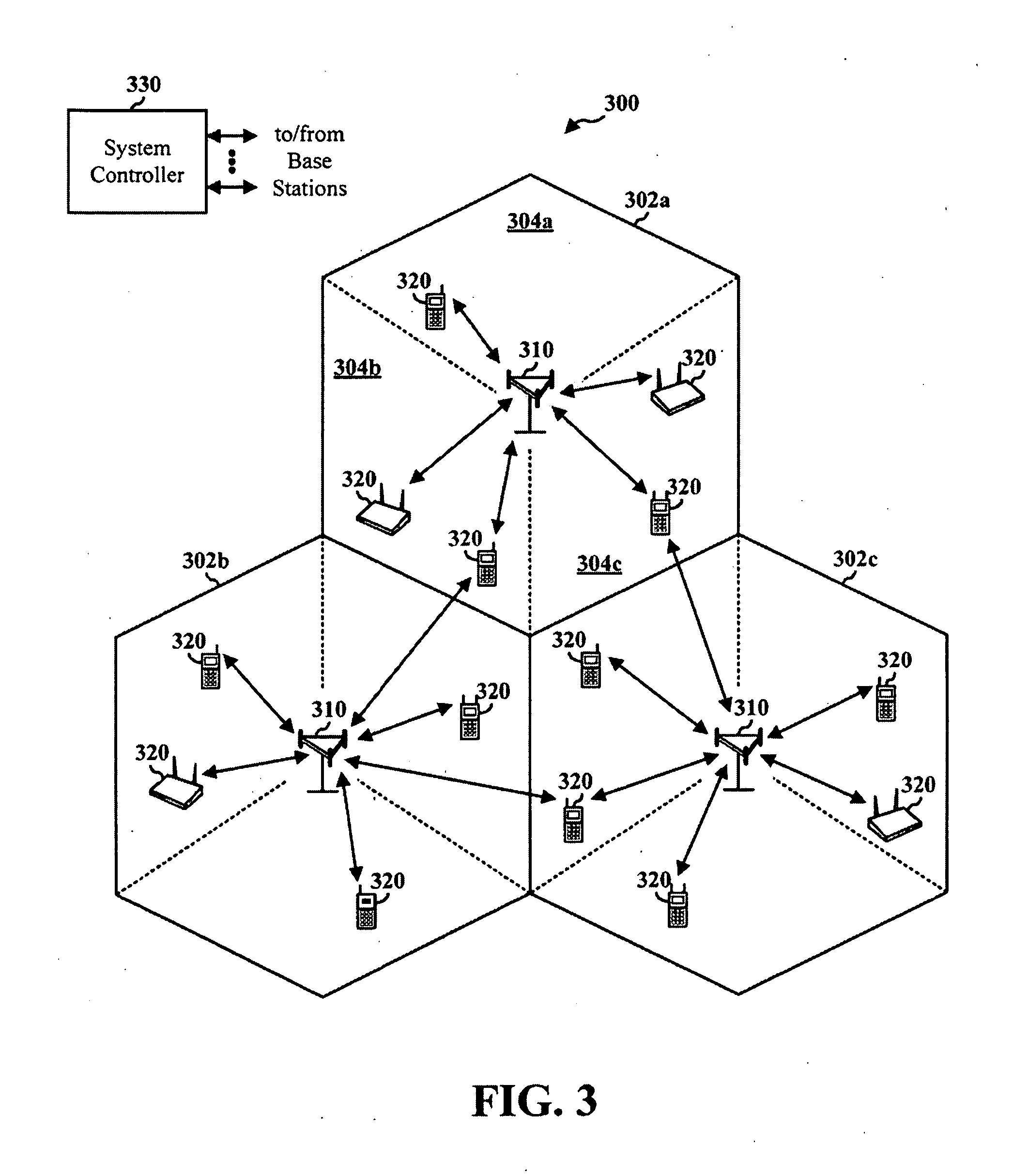
[0038]The claimed subject matter is now described with reference to the drawings, wherein like reference numerals are used to refer to like elements throughout. In the following description, for purposes of explanation, numerous specific details are set forth in order to provide a thorough understanding of the claimed subject matter. It may be evident, however, that the claimed subject matter may be practiced without these specific details. In other instances, well-known structures and devices are shown in block diagram form in order to facilitate describing the claimed subject matter.

[0039]Various embodiments are how described with reference to the drawings, wherein like reference numerals are used to refer to like elements throughout. In the following description, for purposes of explanation, numerous specific details are set forth in order to provide a thorough understanding of one or more aspects. It may be evident however, that such embodiment(s) may be practiced without these ...


PUM


Abstract

Downlink power control commands are mapped to resources used for uplink communications within a wireless communication system. An eNode B receives communications from UEs and determines the resources used by the UEs for those transmissions on the uplink which are transmitted at non-optimum power levels. Power control messages are formulated wherein the location of the power control commands is mapped to particular resources used by the UEs for their uplink transmissions. This facilitates the eNode B to dynamically assign resources for the power control commands while permitting the UEs to decode the power control messages to adjust their power accordingly.

Description

CROSS-REFERENCE TO RELATED APPLICATION(S)[0001]This application claims the benefit of U.S. Provisional Patent Application Ser. No. 60 / 945,325 filed on Jun. 20, 2007 and entitled “METHODS AND APPARATUSES FOR POWER CONTROL,” the entirety of which is incorporated herein by reference.BACKGROUND OF THE INVENTION[0002]Wireless communication systems are widely deployed to provide various types of communications such as voice, data, videos etc. These systems may be multiple-access systems capable of supporting communication with multiple access terminals by sharing available system resources (e.g., bandwidth and transmit power). Examples of such multiple-access systems include code division multiple access (CDMA) systems, time division multiple access (TDMA) systems, frequency division multiple access (FDMA) systems, 3GPP Long Term Evolution (LTE) systems, and orthogonal frequency division multiple access (OFDMA) systems. Typically, a wireless communication system comprises several base sta...

Claims


Application Information

Patent Timeline
IPC IPC(8): G08C17/00
CPCH04W52/146H04W52/54H04W52/58H04W52/34
Inventor DAMNJANOVIC, ALEKSANDAR
Owner QUALCOMM INC
Learn More