
Sealing mechanism for hand-held electric sealer

a technology of sealing mechanism and sealer, which is applied in the direction of transportation and packaging, other domestic articles, packaging, etc., can solve the problems of plastic bags with a single sealing score that may lack sealing reliability, and the goods inside the bags may fall o

Inactive Publication Date: 2008-12-25
CHANG RICHARD
View PDF7 Cites 7 Cited by
  • Summary
  • Abstract
  • Description
  • Claims
  • Application Information

AI Technical Summary

Benefits of technology

[0006]An object of the present invention is to provide an improved sealing mechanism for hand-held electric sealer, so that multiple sealing scores can be made on plastic bags for assuring sealing reliability and durability.
[0009]By means of the above-mentioned improvement in design, the hand-held electric sealer, according to the present invention, provides at least two sealing scores on the plastic bags under sealing, so that the bags to be sealed can have a desirable reliability on the sealing even the sealed bags suffer from a working environment under impact.
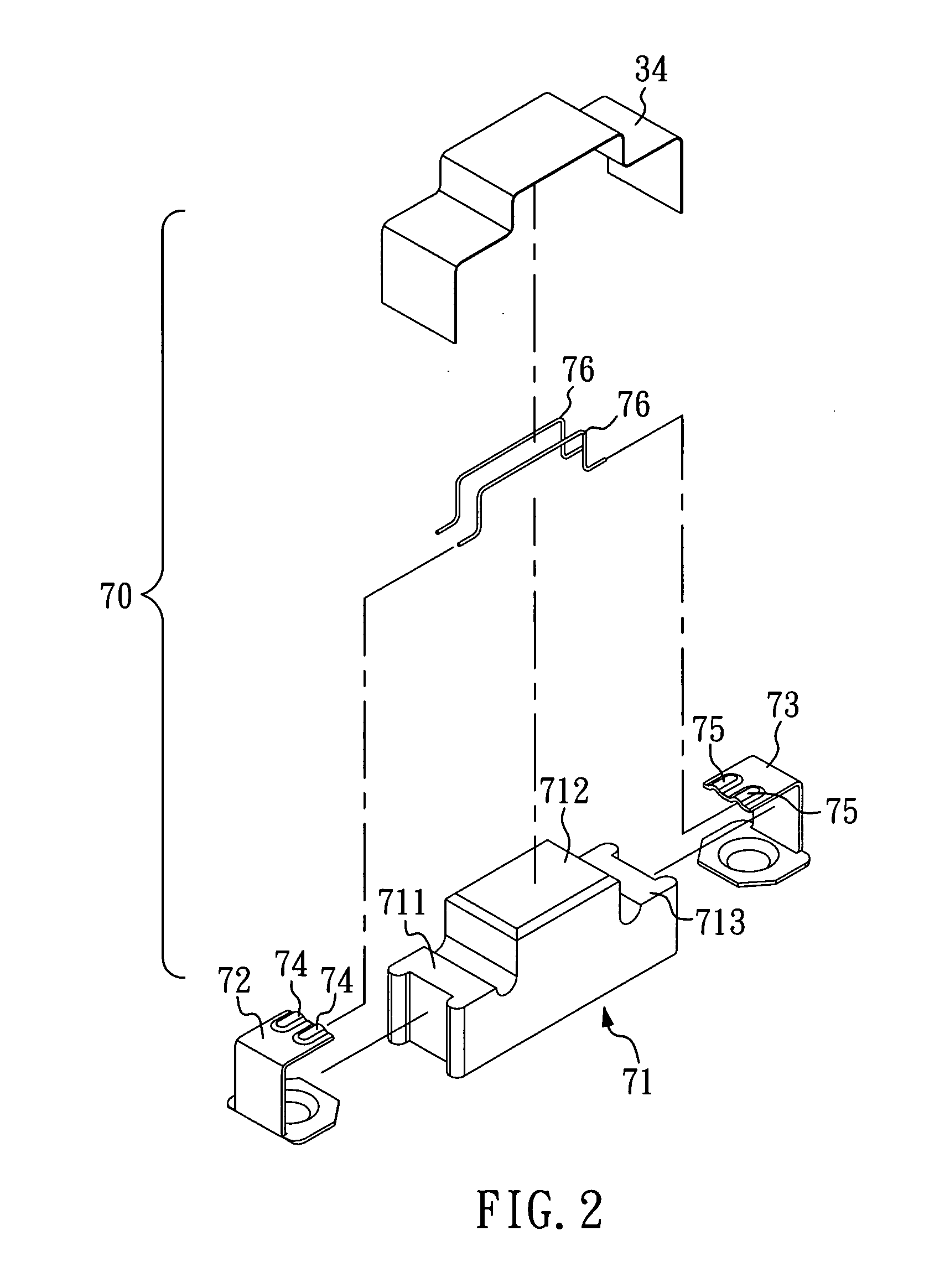
[0010]According to the present invention, the left locating plate and the right locating plate have each a C-shaped cross section, and are engaged with the left side part and the right side part of the heat insulation base, respectively. Further, the left locating plate and the right locating plate of C-shaped cross section have each at least two positioning slots corresponding to the at least two heating wires, such that the heating wires can be inserted into and secured at the positioning slots conveniently and accurately.

Problems solved by technology

However, the plastic bags under a single sealing score may lack sealing reliability, particularly when sealed plastic bags are delivered with carelessness and suffered from an impact.
Under such circumstances, even if the plastic bags are sealed tightly, the sealing may be broken apart due to the impact on the plastic bags, resulting in falling away of the goods inside the bags.

Method used


Image

  • Sealing mechanism for hand-held electric sealer
  • Sealing mechanism for hand-held electric sealer
  • Sealing mechanism for hand-held electric sealer

Examples


Embodiment Construction

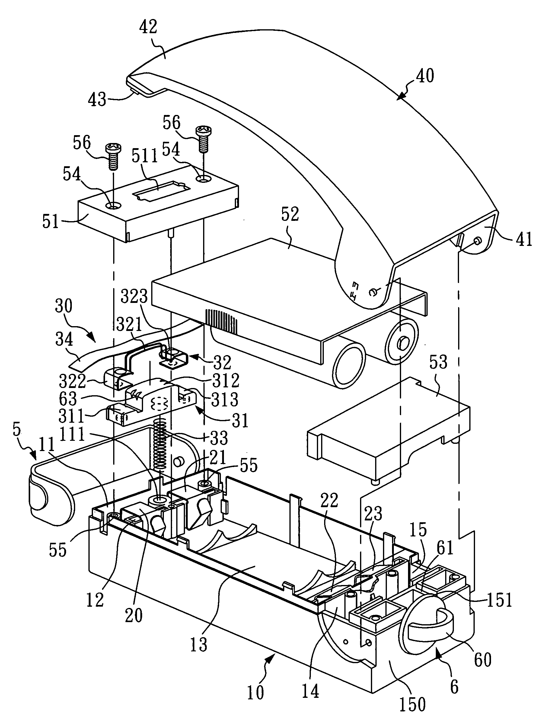
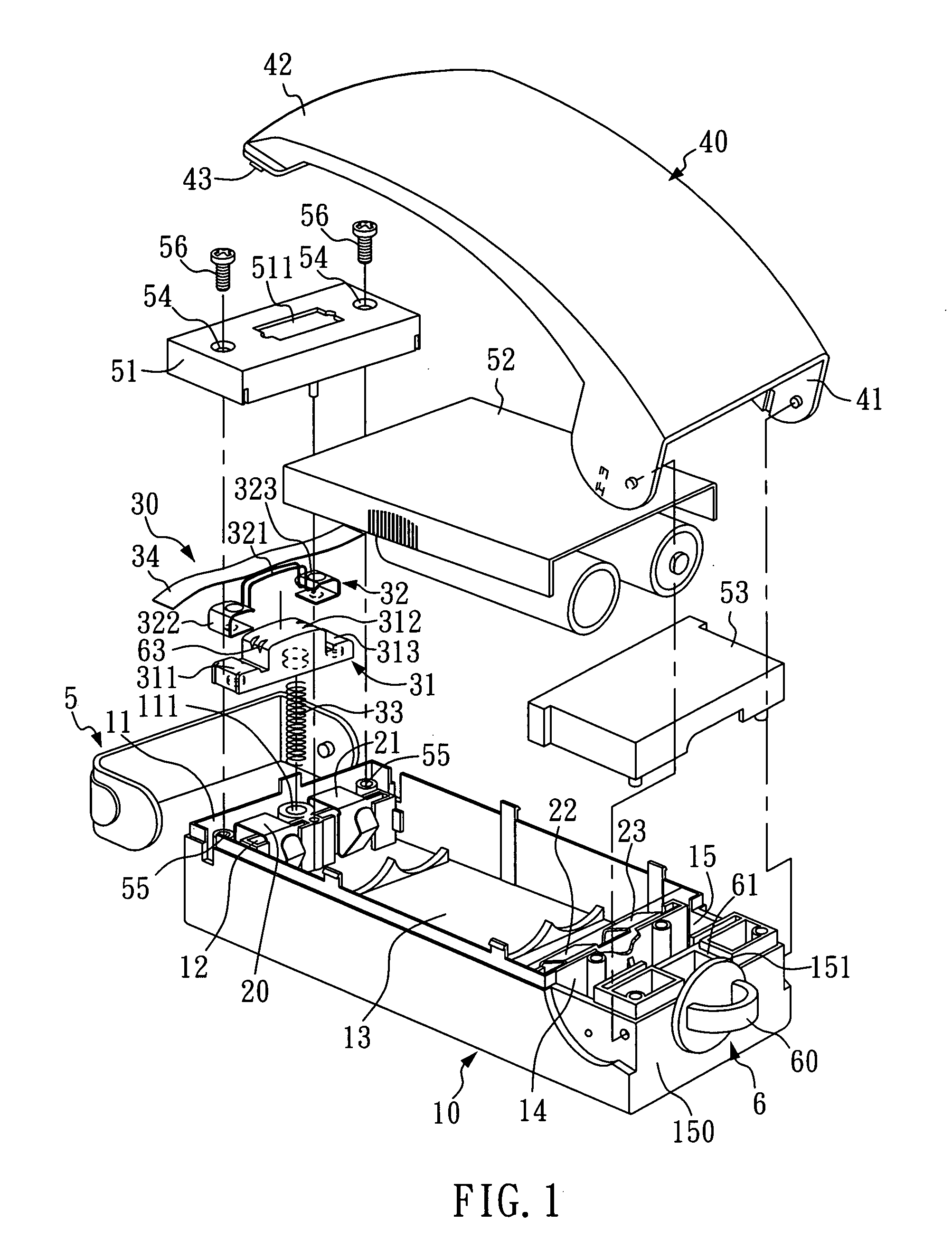
[0026]Referring to FIG. 1, an improved sealing mechanism for hand-held electric sealer according to a first embodiment the present invention comprises a casing 10, a sealing mechanism 30, and a press bar 40. The casing 10 includes a front chamber 11, a front contact holder 12, a battery chamber 13, a rear contact holder 14, and a rear chamber 15. The front chamber 11 is provided with a spring holder 111; a pair of front metal contacts 20, 21 are disposed on the front contact holder 12; and a pair of rear metal contacts 22, 23 are disposed on the rear contact holder 14, wherein the rear metal contacts 22, 23 are connected with each other.

[0027]The sealing mechanism 30 is disposed in the front chamber 11 of the casing 10, and includes a heat insulation base 31 of for example ceramic material, a heating portion 32, and a compression spring 33. The heat insulation base 31 has a left side part 311, a middle part 312, and a right side part 313, which are neighboring to one another sequent...


PUM

PropertyMeasurementUnit
Electrical resistanceaaaaaaaaaa
Heataaaaaaaaaa

Abstract

An improved sealing mechanism includes a heat insulation base, a heating portion, and a compression spring, where the heat insulation base has a left side part, a middle part, and a right side part. The heating portion includes at least two heating wires equidistantly spaced from each other a certain distance, a left locating plate and a right locating plate, where the heating wires are, at both ends, electrically connected with the left locating plate and the right locating plate, respectively. The left locating plate and the right locating plate of the heating portion are engaged with the left side part and the right side part of the heat insulation base, respectively, such that the heating wires are positioned at the middle part of the heat insulation base.

Description

BACKGROUND OF THE INVENTION[0001]1. Field of the Invention[0002]The present invention relates to an improved sealing mechanism for hand-held electric sealer, and more particularly, to a hand-held electric sealer with an improved sealing mechanism having multiple heating wires so as to enhance sealing reliability and durability.[0003]2. Description of Related Art[0004]Nowadays there are several kinds of hand-held electric sealers available in the market. Generally, a conventional hand-held electric sealer comprises a casing, a sealing mechanism, and a press bar. The sealing mechanism includes a heating wire which, after energized by electric power, will be heated sufficiently for sealing plastic bags.[0005]The conventional hand-held electrical sealers achieve the sealing purpose on plastic bags with a single heating wire which produces a single sealing score. However, the plastic bags under a single sealing score may lack sealing reliability, particularly when sealed plastic bags are...

Claims


Application Information

Patent Timeline
IPC IPC(8): H05B1/00B65B51/10
CPCB29C66/0044B29C66/1122B29C66/232B29C66/43121B29C66/8122B29C66/8161B29C66/8167B29C66/861B29C66/8618B29L2031/283B65B51/146B65B51/148B65B67/06B29K2827/18B29C65/00B29C65/223B29C65/225B29C65/228B29C65/222B29C65/224B29C66/81821B29K2909/02B29C66/8324B29C66/8221B29C66/849B29L2031/7128B29C66/8742
Inventor CHANG, RICHARD
Owner CHANG RICHARD
Learn More