Endoscope system
a technology of endoscope and endoscope, which is applied in the field of endoscope system, can solve the problems of difficult accurate grasping, for example, the positional relation between the treatment instrument and the organ
- Summary
- Abstract
- Description
- Claims
- Application Information
AI Technical Summary
Benefits of technology
Problems solved by technology
Method used
Image
Examples
first embodiment
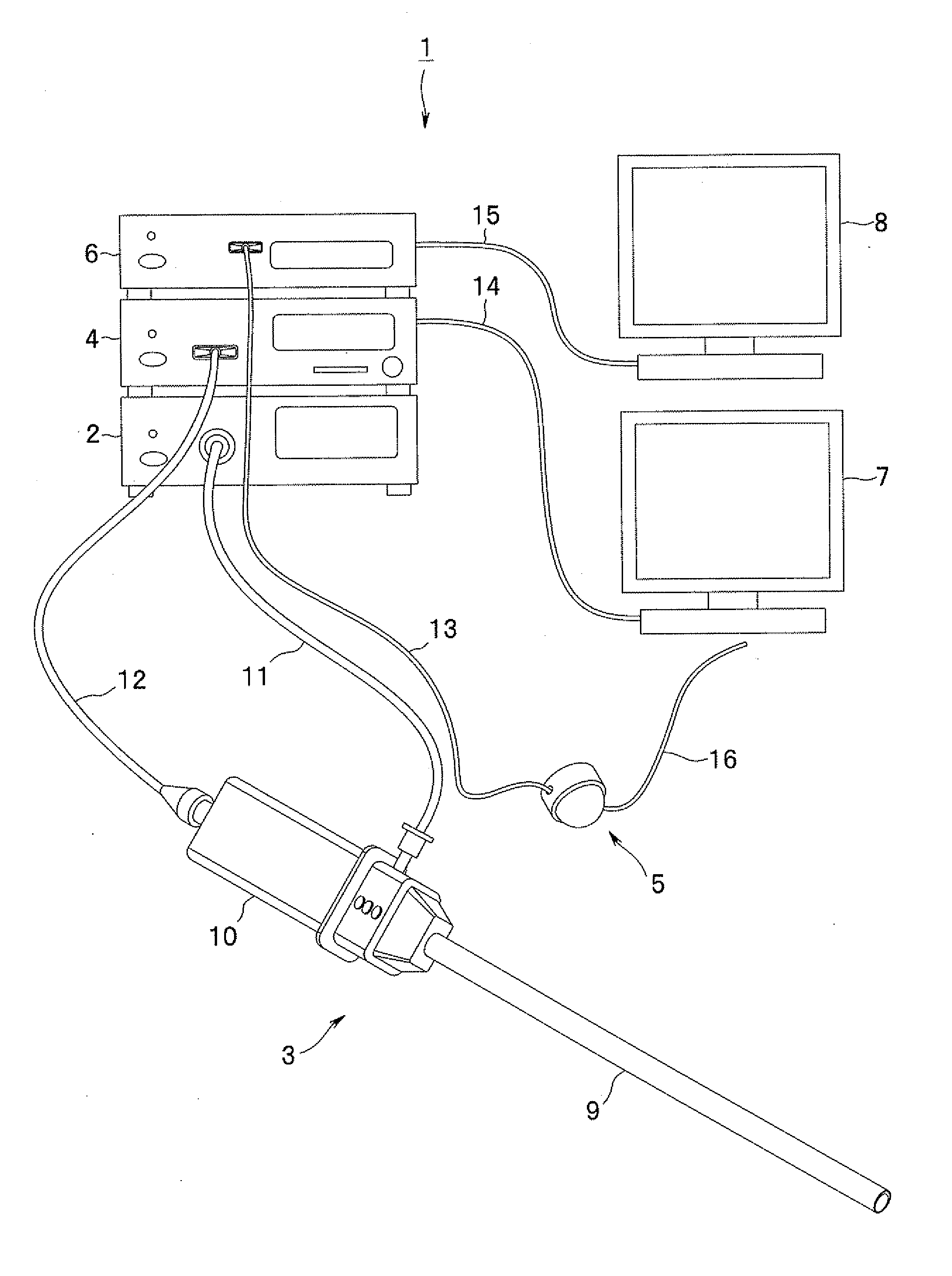
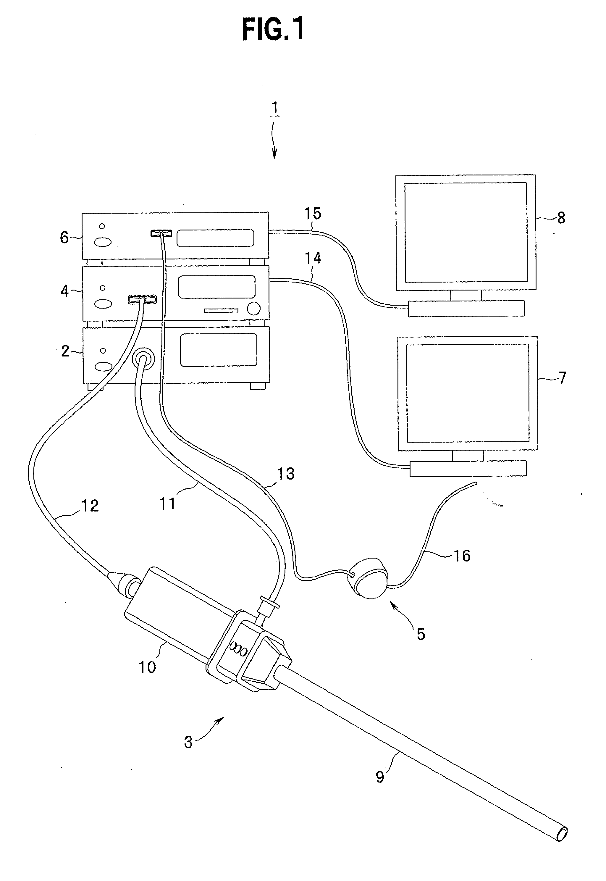
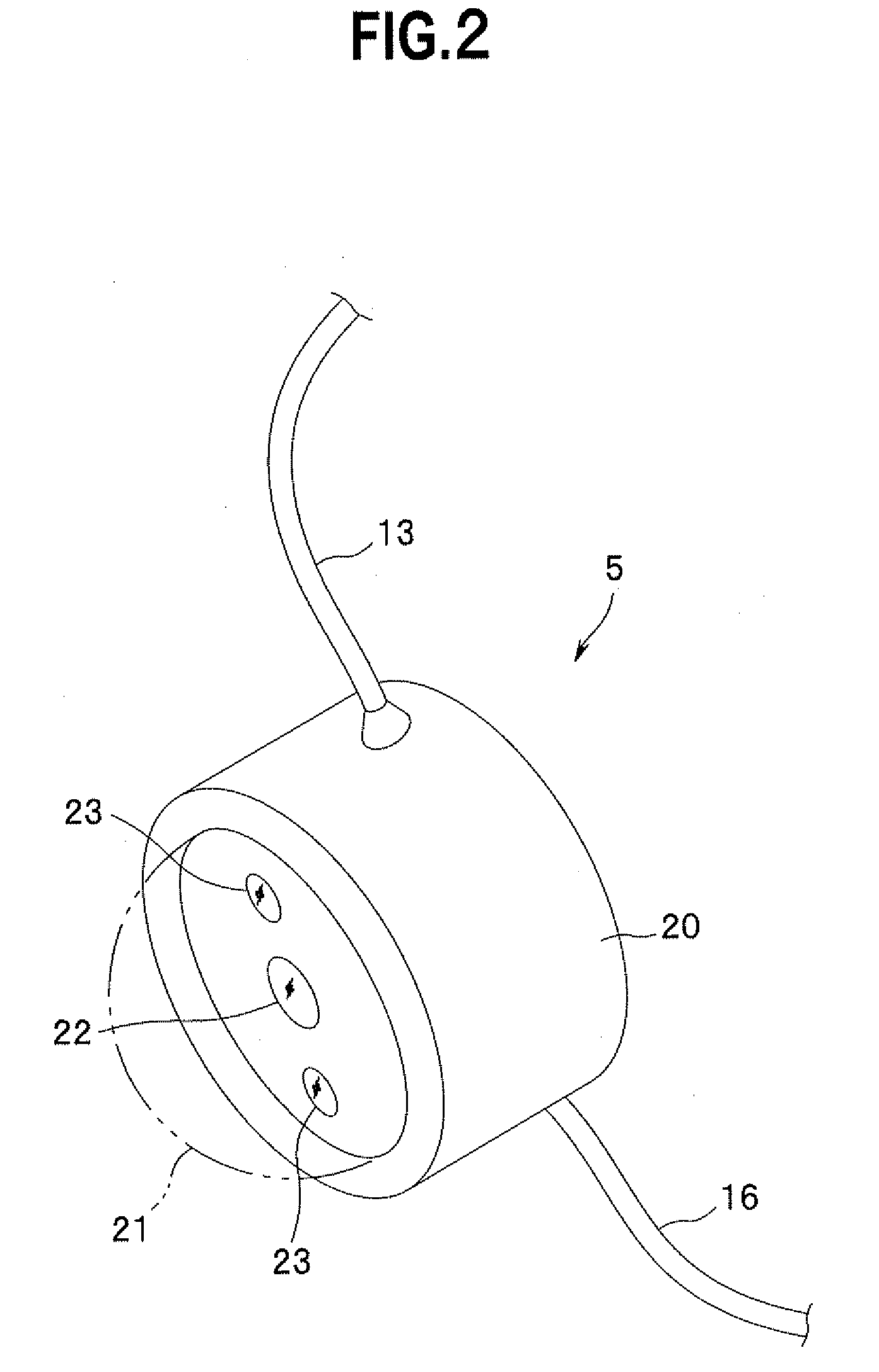
[0023]First, an endoscope system according to a first embodiment of the present invention is explained below. FIGS. 1 to 8 relate to the first embodiment of the present invention. FIG. 1 is a diagram showing a configuration of the endoscope system. FIG. 2 is a perspective view showing a configuration of an intra-body cavity set camera. FIG. 3 is a diagram showing a state in which the endoscope system is set on a patient. FIGS. 4 to 7 are diagrams for explaining a procedure for leading the intra-body cavity set camera into a body cavity. FIG. 8 is a diagram showing view angles of a rigid endoscope and the intra-body cavity set camera set in the body cavity.
[0024]As shown in FIG. 1, an endoscope system I according to the present embodiment for performing a laparoscopic surgical operation mainly includes a light source device 2, a rigid endoscope 3 as a first photographing device, a first camera control unit (hereinafter abbreviated as CCU) 4 as a first signal processing device, an ext...
second embodiment
[0050]An endoscope system according to a second embodiment of the present invention is explained below with reference to FIGS. 9 and 10. FIGS. 9 and 10 relate to the second embodiment of the present invention. FIG. 9 is a diagram showing a state in which the endoscope system is set on a patient. FIG. 10 is a sectional view showing a state in which an intra-body cavity set camera is fixed by an abdominal cavity needle through an abdominal wall. In the following explanation, components identical with those of the endoscope system 1 according to the first embodiment are denoted by the same reference numerals. Detailed explanation of the components is omitted.
[0051]As shown in FIG. 9, the endoscope system 1 according to the present embodiment includes an abdominal cavity needle 51 that is a retaining instrument for fixing and retaining the camera 5 on an inner surface of the abdominal wall 35. As shown in FIG. 10, the abdominal cavity needle 51 includes a needle section 52 projected fro...
third embodiment
[0054]An endoscope system according to a third embodiment of the present invention is explained below with reference to FIGS. 11 and 12. FIGS. 11 and 12 relate to the third embodiment of the present invention. FIG. 11 is a diagram showing a state in which the endoscope system is set on a patient. FIG. 12 is a block diagram showing a state in which an intra-body cavity set camera and a receiving device are fixed by a magnetic force through an abdominal wall. In the following explanation, as in the above explanation, components identical with those of the endoscope system 1 according to the first embodiment are denoted by the same reference numerals. Detailed explanation of the components is omitted.
[0055]The endoscope system 1 according to the present embodiment transits an image of the inside of the abdominal cavity 36 photographed by the camera 5 to the outside of the abdominal cavity 36 by radio. Specifically, as shown in FIG. 11, the camera 5 according to the present embodiment d...
PUM
 Abstract
Description
Claims
Application Information
 - R&D
- Intellectual Property
- Life Sciences
- Materials
- Tech Scout
- Unparalleled Data Quality
- Higher Quality Content
- 60% Fewer Hallucinations
Browse by: Latest US Patents, China's latest patents, Technical Efficacy Thesaurus, Application Domain, Technology Topic, Popular Technical Reports.
© 2025 PatSnap. All rights reserved.Legal|Privacy policy|Modern Slavery Act Transparency Statement|Sitemap|About US| Contact US: help@patsnap.com


