
Ultrasonic diagnostic apparatus and method of measuring velocity with ultrasonic waves

a diagnostic apparatus and ultrasonic wave technology, applied in diagnostics, medical science, applications, etc., can solve the problems of insufficient compensation of the velocity of blood flow obtained by the doppler angle correction in the two-dimensional ultrasonic sectional image data, the inability to directly measure the velocity in the direction of blood flow, and the inability to accurately measure the velocity of blood flow obtained by the doppler angle correction

Inactive Publication Date: 2008-12-11
KK TOSHIBA +1
View PDF3 Cites 54 Cited by
  • Summary
  • Abstract
  • Description
  • Claims
  • Application Information

AI Technical Summary

Benefits of technology

[0038]FIG. 22 is a schematic diagram showing a transmitter-receiver and

Problems solved by technology

However, as an ultrasonic Doppler diagnostic apparatus is influenced by an angle formed by a blood flow direction and a direction of a wave reflected from a blood flow, it is difficult to directly measure the velocity in the direction of blood flow.
However, the velocity of blood flow obtained by the Doppler angle correction in the two-dimensional ultrasonic sectional image data is insufficient to compensate for the influence in the depth direction that is a three-dimensional direction.
Thus, the velocity of blood flow obtained by the Doppler angle correction lacks reliability.

Method used


Image

  • Ultrasonic diagnostic apparatus and method of measuring velocity with ultrasonic waves
  • Ultrasonic diagnostic apparatus and method of measuring velocity with ultrasonic waves
  • Ultrasonic diagnostic apparatus and method of measuring velocity with ultrasonic waves

Examples


first embodiment

[0039]Hereinafter, an explanation will be given on the invention with reference to the accompanying drawings.

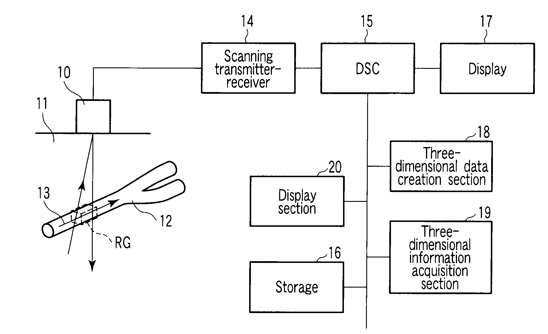
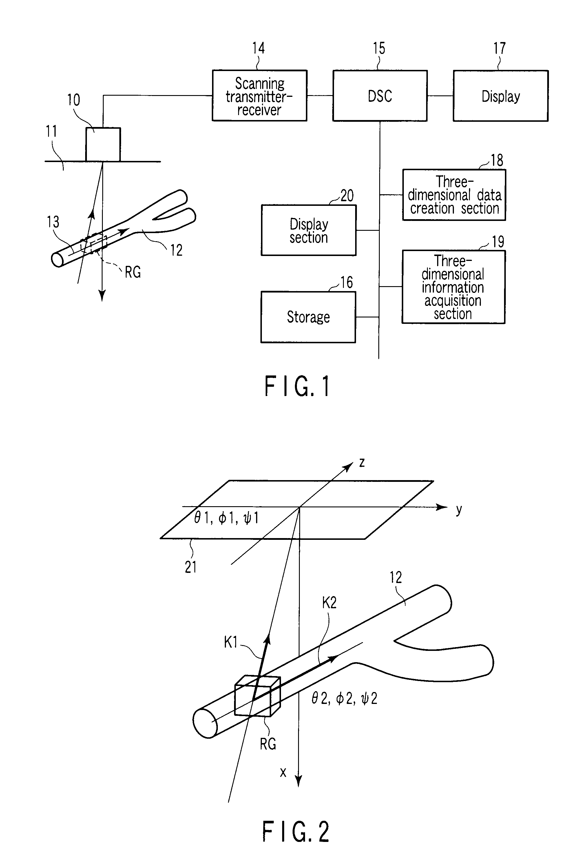
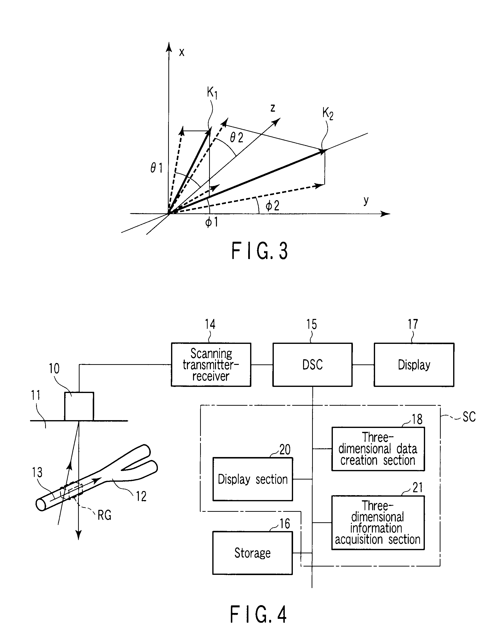
[0040]FIG. 1 is a block diagram of an ultrasonic Doppler diagnostic apparatus. An ultrasonic probe 10 emits a multiple ultrasonic beam pulse consisting of a plurality of beams to a specific area including a sample 13 (hereinafter called a range gate RG), and receives a wave reflected from the range gate RG. The sample 13 is fluid such as blood flowing in a blood vessel 12 in a living body 11 such as a human body. The ultrasonic probe 10 is composed of ultrasonic oscillators arranged on a two-dimensional plane. The ultrasonic probe 10 transmits a multiple ultrasonic beam, and receives waves reflected from the ultrasonic oscillators.

[0041]A scanning transmitter-receiver 14 electrically scans the ultrasonic oscillators of the ultrasonic probe 10, thereby sequentially driving the ultrasonic oscillators and outputting a multiple ultrasonic beam for scanning. The scanning transmitt...


PUM


Abstract

A multiple ultrasonic beam is transmitted from an ultrasonic probe, and a velocity of blood flow, azimuth and elevation angle of a sample such as a blood flow are acquired by a three-dimensional information acquisition section, as three-dimensional fluid information in a range gate, based on a Doppler signal output from the ultrasonic probe.

Description

CROSS-REFERENCE TO RELATED APPLICATIONS[0001]This application is based upon and claims the benefit of priority from prior Japanese Patent Application No. 2007-149466, filed Jun. 5, 2007, the entire contents of which are incorporated herein by reference.BACKGROUND OF THE INVENTION[0002]1. Field of the Invention[0003]The present invention relates to Doppler angle correction for obtaining an absolute value of a velocity of blood flow by measuring a Doppler angle. In particular, the present invention relates to an ultrasonic diagnostic apparatus, which measures a velocity of a sample such as fluid, for example, blood flowing in a living body such as a human body, and a method of measuring a velocity with ultrasonic waves.[0004]2. Description of the Related Art[0005]An ultrasonic Doppler diagnostic apparatus emits an ultrasonic beam into a living body, and receives a wave reflected from blood flowing in a blood vessel in a living body, for example. An ultrasonic Doppler diagnostic appara...

Claims


Application Information

Patent Timeline
IPC IPC(8): A61B8/06
CPCA61B8/06
Inventor BABA, TATSUROOGASAWARA, YOICHI
Owner KK TOSHIBA
Learn More