Digitally controlled antenna tuning circuit for radio frequency receivers
- Summary
- Abstract
- Description
- Claims
- Application Information
AI Technical Summary
Benefits of technology
Problems solved by technology
Method used
Image
Examples
first embodiment
Antenna Tuning Circuit
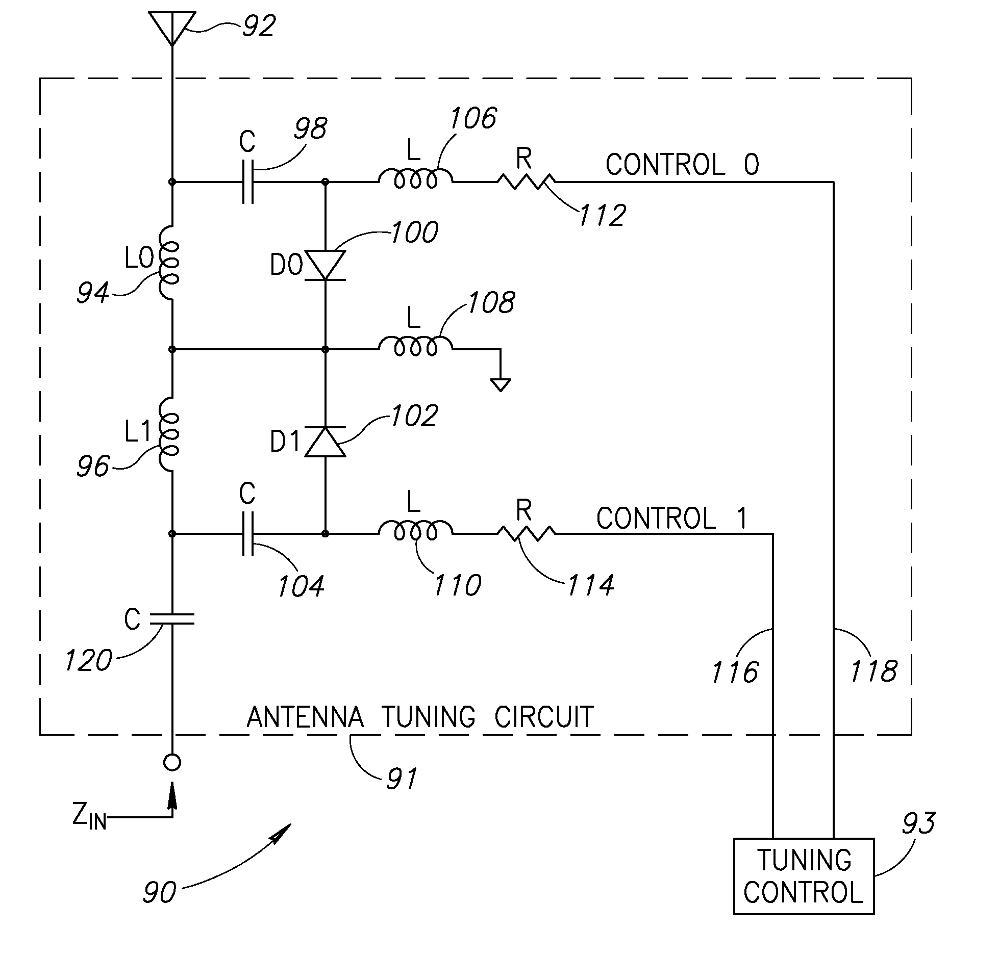
[0067]A schematic diagram illustrating a first example embodiment of the antenna tuning circuit of the present invention having series connected tuning elements is shown in FIG. 5. The circuit, generally referenced 90, comprises a tuning circuit 91 coupled to antenna 92 and a tuning control circuit 93. The tuning circuit comprises two series connected tuning stages comprising tuning elements made up of inductors L0 (94), L1 (96), DC blocking capacitors C 98, 104, 120, RF chokes L 106, 108, 110, resistors R 112, 114 and switching devices comprising PIN diodes D0 (100), D1 (102).
[0068]In accordance with the invention, it is assumed that the signals flowing through the main receive signal path are sufficiently weak enough to allow the use of a single PIN diode to short circuit a single tuning stage. In the example circuit 90, the main receive signal path comprises two tuning elements connected in series (L0 and L1).
[0069]Two switching elements comprising PIN diode...
second embodiment
Antenna Tuning Circuit
[0075]A schematic diagram illustrating a second example embodiment of the antenna tuning circuit of the present invention having series connected tuning elements is shown in FIG. 6. The circuit, generally referenced 220, comprises a tuning circuit 221 coupled to antenna 222 and a tuning control circuit 223. The tuning circuit comprises four series connected tuning stages comprising tuning elements made up of inductors L0 (224), L1 (226), L2 (228), L3 (230), DC blocking capacitors C 232, 242, 246, 252, 256, 266, RF chokes L 236, 240, 260, 258, 268, resistors R 238, 250, 262, 270 and switching devices comprising PIN diodes D0 (234), D1 (244), D2 (254), D3 (264).
[0076]In this example circuit 221, four tuning stages comprising tuning elements L0, L1, L2 and L3 are connected in series to form the main receive signal path. Corresponding PIN diodes D0, D1, D2 and D3 connected in parallel to the tuning elements act as switches to switch each respective tuning element e...
third embodiment
Antenna Tuning Circuit
[0077]A schematic diagram illustrating a third example embodiment of the antenna tuning circuit of the present invention having series connected tuning elements is shown in FIG. 7. The circuit, generally referenced 130, comprises a tuning circuit 131 coupled to antenna 132 and a tuning control circuit 133. The tuning circuit comprises two series connected tuning stages comprising tuning elements made up of capacitors C0 (134), C1 (136), DC blocking capacitor C 138, RF chokes L 144, 148, 150, resistors R 146, 152 and switching devices comprising PIN diodes D0 (140), D1 (142).
[0078]In this example circuit 131, two tuning stages comprising tuning elements capacitors C0 and C1 are connected in series to form the main receive signal path rather than inductors as in the example circuits 91 (FIG. 5) and 221 (FIG. 6). Corresponding PIN diodes D0 and D1 connected in parallel to the tuning elements act as switches to switch each respective tuning element either into or o...
PUM
 Abstract
Description
Claims
Application Information
 - R&D
- Intellectual Property
- Life Sciences
- Materials
- Tech Scout
- Unparalleled Data Quality
- Higher Quality Content
- 60% Fewer Hallucinations
Browse by: Latest US Patents, China's latest patents, Technical Efficacy Thesaurus, Application Domain, Technology Topic, Popular Technical Reports.
© 2025 PatSnap. All rights reserved.Legal|Privacy policy|Modern Slavery Act Transparency Statement|Sitemap|About US| Contact US: help@patsnap.com


