
Image Processing Method, Program Thereof, and Image Forming Apparatus

Inactive Publication Date: 2008-12-11
RICOH KK
View PDF2 Cites 13 Cited by
  • Summary
  • Abstract
  • Description
  • Claims
  • Application Information

AI Technical Summary

Benefits of technology

[0032]The present invention may solve one or more of the problems in the conventional technologies. According to embodiments of the present invention, there is provided an image processing method, a program thereof, and an image forming apparatus, in which both high printing speed and high image quality are realized.
[0041]According to the image processing method, the program thereof, and the image forming apparatus in the embodiments of the present invention, when one or more dots near a step-shaped changing part of an outline part of an image are converted into a predetermined dot, one or more dots to be converted are detected by using an “m×n” dot window in which the number of dots “m” corresponds to the resolution in the first direction and the number of dots “n” corresponds to the resolution in the second direction. Therefore, both high printing speed and high image quality are realized.

Problems solved by technology

However, when piezoelectric elements are used as a pressure generating unit which generates an ink droplet ejecting force in a recording head, there is a limitation to making the nozzle density high.
Therefore, when an image is formed by the one-path non-interlaced system, the resolution of the image is inevitably lowered.
A high quality image can be formed for an image such as a photograph by using the multi-level dots; however, the multi-level-dot method is hardly effective for letters and graphics.
Consequently, in a binary image such as letters and graphics, a problem peculiar to the low resolution occurs.
Especially, in the case of the letter, letter quality is degraded and the letter is hardly readable.
However, a jaggy-correcting technology described in Patent Documents 1 through 3 cannot be applied to an image forming apparatus which forms an image by using ink droplets of recording liquid.
In addition, when the image forming apparatus using recording liquid is compared with a laser printer or an LED printer, in the image forming apparatus using the recording liquid, since it needs more time to form a dot, it is difficult to have various dot sizes which are changed by the number and the length of driving pulses during a driving cycle, and a few dot sizes can be used at most.
In addition, an LED printer or a laser printer can change a dot position relatively freely in a pixel; however, in the image forming apparatus using the recording liquid, the dot position is determined at an almost fixed position in a pixel and cannot be changed relatively freely in the pixel.
However, in the smoothing method called the anti-aliasing method, as described in Patent Document 5, since the outline part is formed by dots having great number of gradations, the smoothing can be executed highly accurately; however, the processes are complex and a long processing time is required.
Therefore, the method is not suitable for a recently produced image forming apparatus such as an inkjet recording apparatus which needs high throughput.
However, since nozzle resolution is low caused by a limitation of a nozzle arraying pitch, when it is attempted to make resolution in the sub scanning direction (paper carrying direction) high, dots are formed by plural scanning.
Consequently, recording speed is lowered and it is extremely difficult to realize both high speed printing and high resolution.
However, in this case, since the resolution in the main scanning direction becomes high, depending on an angle of an outline part of an image, the outline part is changed in a step shape with high resolution and Bagginess is not noticeable; however, depending on another angle, the outline part is changed in a step shape with low resolution and jagginess is noticeable.
Consequently, in the conventional technologies, a process for smoothing becomes complex due to high resolution in one direction, cost increases for installing additional memories, and printing time increases caused by the increase in processing time.

Method used


Image

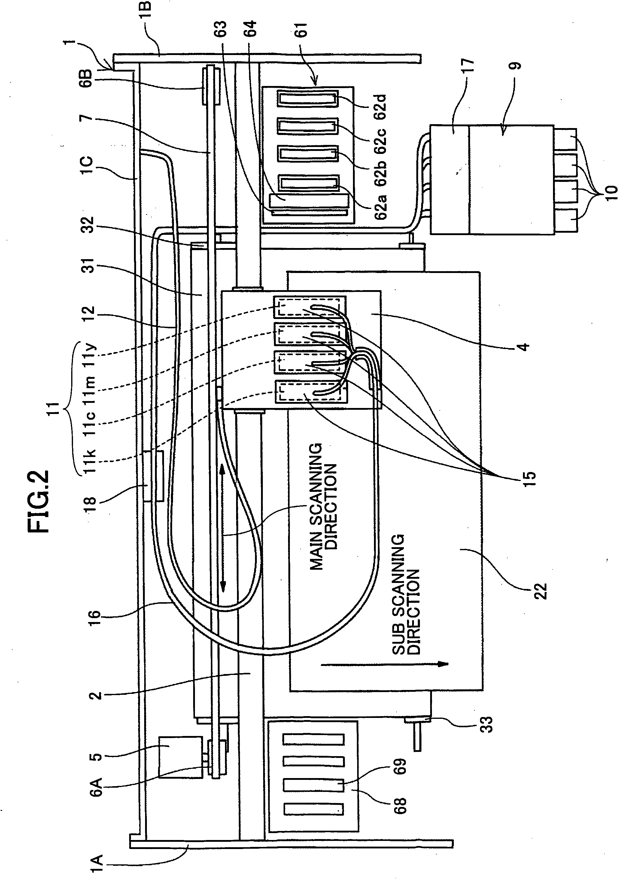
  • Image Processing Method, Program Thereof, and Image Forming Apparatus
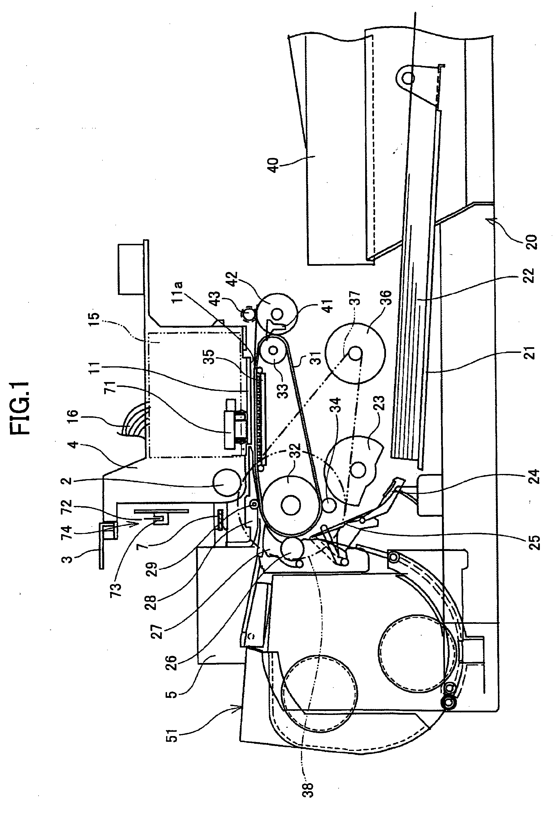
  • Image Processing Method, Program Thereof, and Image Forming Apparatus
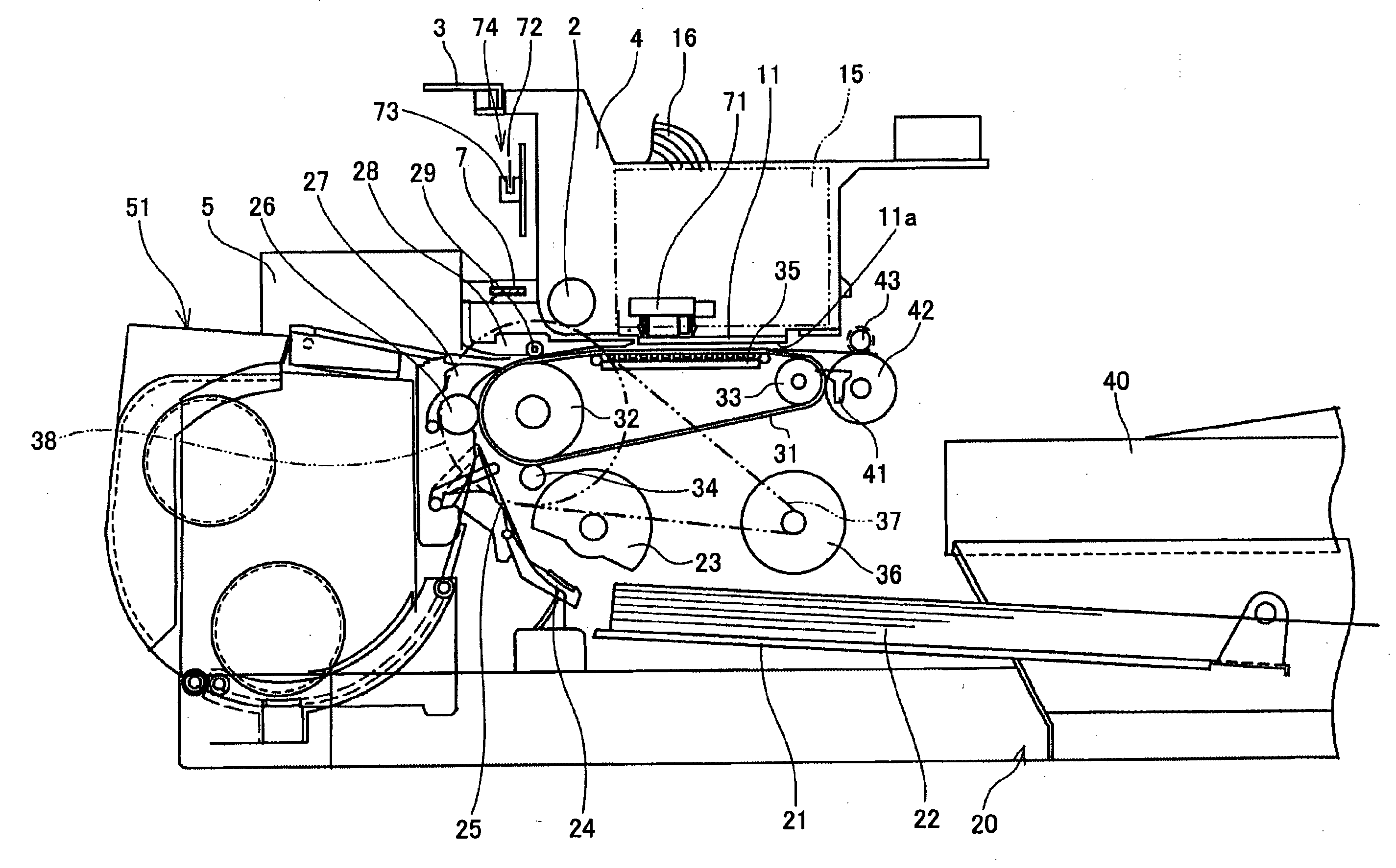
  • Image Processing Method, Program Thereof, and Image Forming Apparatus

Examples


first embodiment

[0224]Next, referring to FIG. 27, a pattern matching process (method) (dot data converting process) which is executed by the printer driver is explained. FIG. 27 is a flowchart showing the pattern matching process according to the present invention. In this, as the small dot, the small ink droplet dot is used.

[0225]First, a dot positioned in front of the head of font data is selected as a target pixel. Next, bit map data of the font data corresponding to a window are obtained by setting the target pixel as the center. The bit map data obtained at this time are data of 27 dots (9 dots×3 dots).

[0226]Next, the obtained bit map data are compared with data of a predetermined pattern (reference pattern) by the pattern matching method. The reference pattern is a dot addition pattern or a small dot conversion pattern. When both the data are matched with each other, the target pixel data are converted into small dot data. In this, the small dot data are small ink droplet dot data.

[0227]When ...

second embodiment

[0261]Next, referring to FIGS. 36 through 43, examples of the jaggy correction according to the present invention are explained in detail. In FIGS. 36 through 43, a first example through an eighth example of the jaggy correction are shown, respectively. As described above, in FIGS. 36 through 43, the pitch between adjacent two dots shown by the same interval is 600 dpi in the main scanning direction and 300 dpi in the sub scanning direction on an actual recording medium. In addition, a dot formed by a small ink droplet is called a small dot, and a dot formed by a medium ink droplet is called a medium dot, and the sizes of the small dot and the medium dot are smaller than the size of dots which form the step-shaped changing part.

[0262]In FIG. 36, a small ink droplet dot is added to blank dots D46 and D61 at changing points of the step-shaped changing parts. In FIG. 37, a small ink droplet dot is added to blank dots D45 and D62 and a medium ink droplet dot is added to the blank dots D...


PUM


Abstract

An image processing method is disclosed. The image processing method includes the steps of detecting one or more dots near a step-shaped changing part of dots of which an outline part of a letter or graphics is composed, by using a reference pattern having a window size of “m×n” dots in which a number of dots “m” corresponds to resolution in the main scanning direction and a number of dots “n” corresponds to resolution in the sub scanning direction, converting the detected one or more dots near the step-shaped changing part that is nearly parallel to the main scanning direction into a dot whose size is smaller than that of dots of the step-shaped changing part, and not converting the detected one or more dots whose part is nearly parallel to the sub scanning direction.

Description

TECHNICAL FIELD[0001]The present invention generally relates to an image processing method, a program thereof, and an image forming apparatus.BACKGROUND ART[0002]As an image forming apparatus such as a printer, a facsimile, a duplicating apparatus, a plotter, and a multifunctional apparatus combining the printer, the facsimile, and the duplicating apparatus, there is an inkjet recording apparatus. The inkjet recording apparatus includes an image forming unit which ejects ink droplets of recording liquid and can form an image on a recording medium such as a paper by ejecting the ink droplets from the image forming unit on the recording medium. In this, the image forming signifies image printing, image recording, letter printing, and image transferring.[0003]Of such image forming apparatuses, there are a serial type image forming apparatus and a line type image forming apparatus. The serial type image forming apparatus forms one line of an image by moving a recording head in the width...

Claims


Application Information

Patent Timeline
IPC IPC(8): G06T5/00
CPCB41J2/04581B41J2/04588B41J2/04593G06K15/102G06K2215/006G03G21/00B41J2/01
Inventor KIMURA, TAKASHI
Owner RICOH KK
Learn More