
Illumination Control Apparatus Using a Pulsating Waves

Inactive Publication Date: 2008-12-11
KIM & JONG +2
View PDF2 Cites 2 Cited by
  • Summary
  • Abstract
  • Description
  • Claims
  • Application Information

AI Technical Summary

Benefits of technology

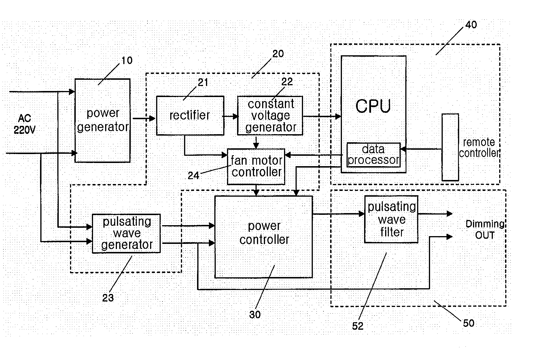
[0013]Accordingly, it is an object of the present invention to provide an illumination control apparatus using a pulsating wave in which a pulsating power is supplied to the electric power supplied to a fluorescent light stabilizer that needs an AC voltage, the level of the same is varied and supplied, an illumination control, such as fluorescent light and common light, is possible based on an input power control of a stabilizer without changing an installation of a conventional fluorescent light and common light device and the power construction. In addition, the electric power can be concurrently supplied to a plurality of stabilizers based on a capacity of apparatus without changing the construction of a conventional system.

Problems solved by technology

In particular, in the case of an open store built on the ground, it is needed to keep a high illumination state for 24 hours using a luminance discharge light with low power consumption, so that over power is consumed.
So, power consumption increases, and the system is complicated, and more cost is needed.
The above method is not easy to continuously adjust brightness, and efficiency decreases.
So, this method is not currently used.
The construction is complicated, so that it may be very expensive.
However, the method by a phase control and a reverse phase control method have the following problems.
Since the voltage supply is performed with a high voltage, voltage impact may occur in the load.
In a worse case scenario, the load may be damaged by the voltage impact, and / or harmonic frequency may occur.
However, the above methods have problems as well.
Such noises may be big problems depending on the kinds of loads.
In case that the load is lighting and the lighting is used indoor, the problems are very serious.
As shown in FIG. 14, the reverse phase control method may supply non-uniform electric power owing to counter electro-motive force with respect to a blank time period of electric power since a turn off / on time of the control point during the control operation.
In lower stages, the control problem increases.
Critical errors may occur in the stabilizer of load because of high frequency at a basic control point.
However, when the AC voltage is introduced at the lower stages during the dimming control of the above method, a flickering and trembling phenomenon occurs, due to the discharge in the case of fluorescent light, so that the life span of tube may decrease.
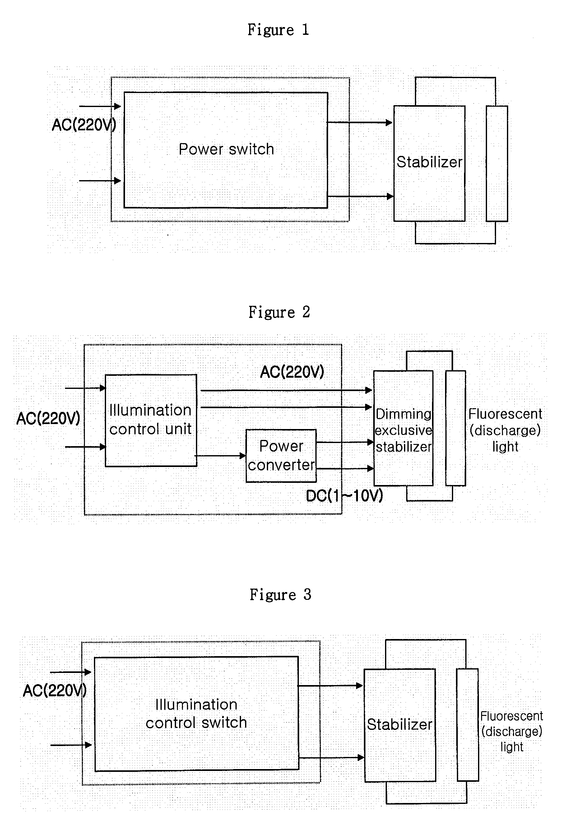
Since a DC converter is necessarily attached to the stabilizer for a dimming operation, as shown in FIG. 1, there may be many problems in construction, when it is adapted to a facility of conventional fluorescent light.
When it is newly adapted, an expensive system control apparatus is needed for thereby increasing the expenditure.
Since the change of the electric level is less based on the change of the illumination during the installation, only indirect lighting effect can be obtained irrespective of the effect of cost down of electric power, so that it is impossible to obtain an electric power saving effect.

Method used


Image

  • Illumination Control Apparatus Using a Pulsating Waves
  • Illumination Control Apparatus Using a Pulsating Waves
  • Illumination Control Apparatus Using a Pulsating Waves

Examples


Embodiment Construction

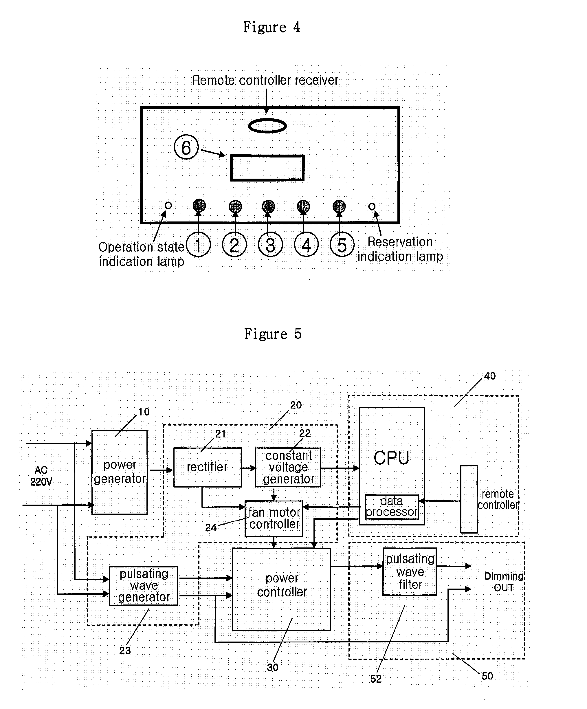
[0029]FIG. 4 is a view illustrating an outer construction of a main switch during an actual installation of an illumination control apparatus according to the present invention. Provided are an; on and off switch for illumination control, an up and down level switch, a temporal level setting switch, a reservation off switch, an illumination level and illumination reservation display, a remote controller receiver and an operation state indication light.

[0030]Here, the on and off switch performs an on and off function of power as a main switch, and the up and down level switch allows a user to control the intensity of the illumination, and the temporal level setting switch selects a certain illumination level in a switch on switch, so that the selected illumination level can begin when the system is turned on after a switch off.

[0031]The reservation off switch is provided for reserving the time of power off.

[0032]The illumination level and illumination display is a window for visually...


PUM


Abstract

An illumination control apparatus using a pulsating wave is disclosed, in which a pulsating power is supplied to an electric power supplied to a fluorescent light stabilizer which needs an AC voltage. The level of the same is varied and supplied to an illumination control, such as fluorescent light and common light, is possible based on an input power control of a stabilizer without changing an installation of a conventional fluorescent light and common light device and of the power construction. In addition, the electric power can be concurrently supplied to a plurality of stabilizers based on a capacity of apparatus without changing the construction of a conventional system.

Description

TECHNICAL FIELD[0001]The present invention relates to an illumination control apparatus using a pulsating wave, and in particular to an illumination control apparatus using a pulsating wave in which a spot flash and illumination control are possible for a lamp connected on a single cable without a special stabilizer.BACKGROUND ART[0002]Over power consumption is performed due to a high illumination using a T5 fluorescent light (deco lamp / slim light) and high electric power bulb in consideration with an imitation of a store such as a commercial store including home. In particular, in the case of an open store built on the ground, it is needed to keep a high illumination state for 24 hours using a luminance discharge light with low power consumption, so that over power is consumed. In addition, an adaptor for a power converter and a high capacity of current DC motor and an inverter having a simple power converter function are used for convenience. So, power consumption increases, and t...

Claims


Application Information

Patent Timeline
IPC IPC(8): G05F1/66H05B37/02
CPCH05B37/0245H05B39/047H05B47/175Y02B20/00F24F7/065F24F13/10F24F3/167
Inventor KIM, SI JONGBAIK, SUNG HYUNHWANG, JAE WON
Owner KIM & JONG
Learn More