
Method and Apparatus For Humidification of Breathable Gas With Profiled Delivery

Active Publication Date: 2008-12-11
RESMED LTD
View PDF24 Cites 46 Cited by
  • Summary
  • Abstract
  • Description
  • Claims
  • Application Information

AI Technical Summary

Benefits of technology

[0012]Another aspect of the invention reduces water or fluid volume required by maximizing efficient use of water, which is a form of ‘rationing’.

Problems solved by technology

However, the intention is not to replace conventional, continuously heated humidifiers, but rather to provide an additional choice more suitable for certain patients.

Method used


Image

  • Method and Apparatus For Humidification of Breathable Gas With Profiled Delivery
  • Method and Apparatus For Humidification of Breathable Gas With Profiled Delivery
  • Method and Apparatus For Humidification of Breathable Gas With Profiled Delivery

Examples


Embodiment Construction

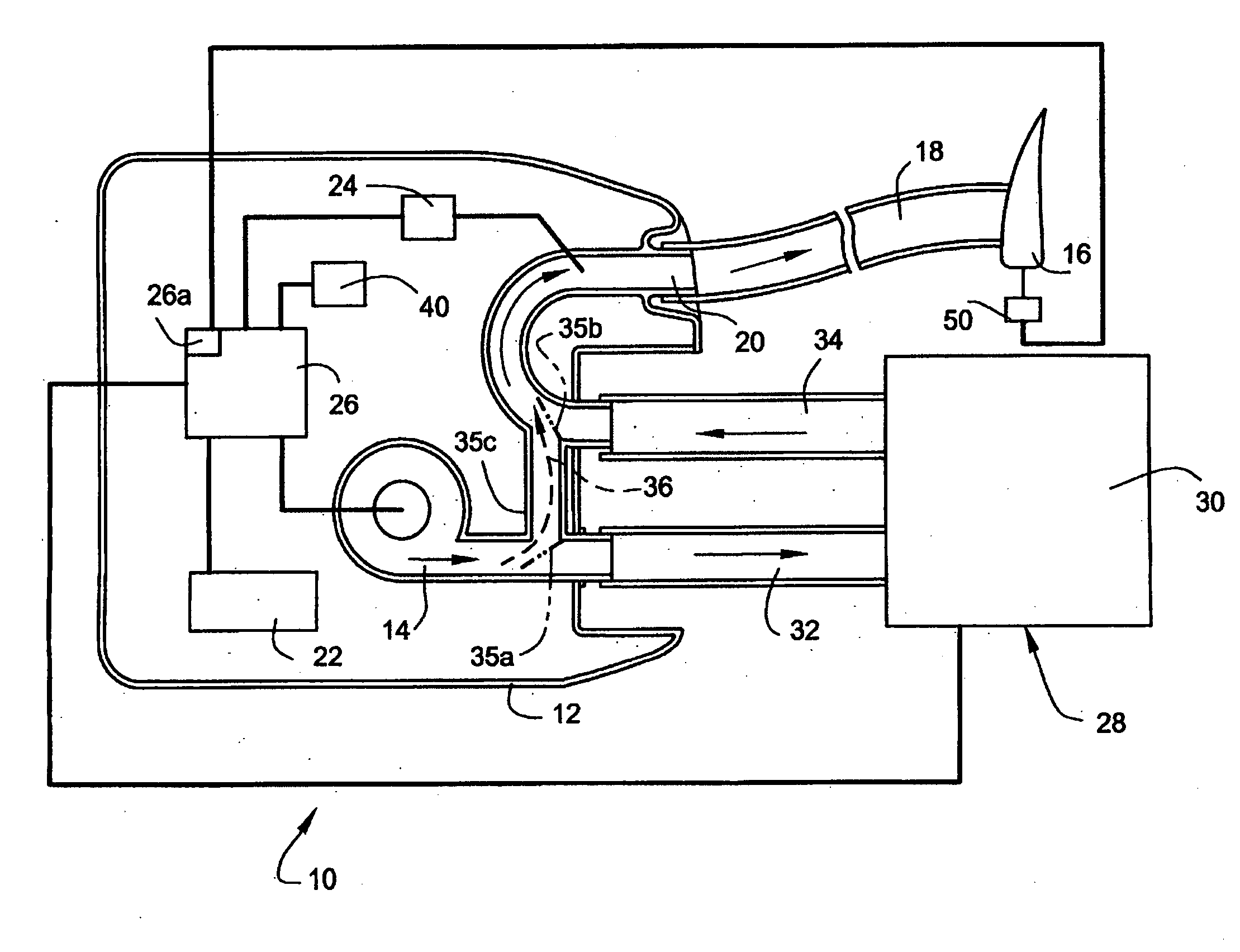
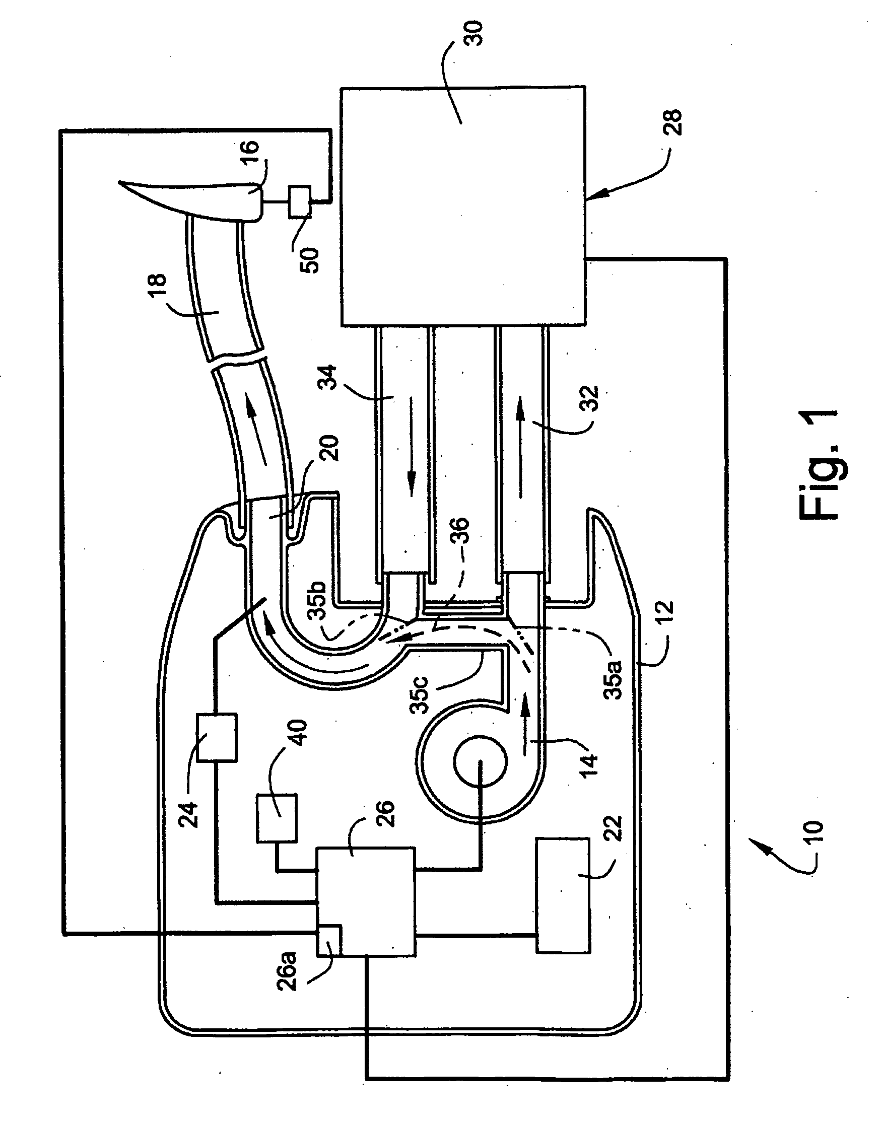
[0018]FIG. 1 schematically illustrates a blower 10 according to an embodiment of the present invention. Blower 10 typically includes a housing 12 to support a blower motor 14 that pressurizes breathable gas for delivery to a patient interface 16 (e.g., a mask) via an air delivery conduit 18 that is connected to an outlet conduit 20 of blower 10. Blower 10 includes a control panel 22 with one or more buttons and preferably a display. Blower 10 includes a pressure sensor 24 to provide a signal to a controller 26 (e.g., CPU) for control of blower motor 14, in accordance with one or more control algorithms commercially available from ResMed, Inc.

[0019]Blower 10 is optionally provided with a selectively attachable and detachable humidifier unit 28 that includes a tub 30 and one or more conduits 32, 34 that communicate with blower 10. Humidifier unit 28 may include structure as detailed in U.S. Published Patent Application No. 2004 / 0055597A1, incorporated by reference in its entirety. Hum...


PUM


Abstract

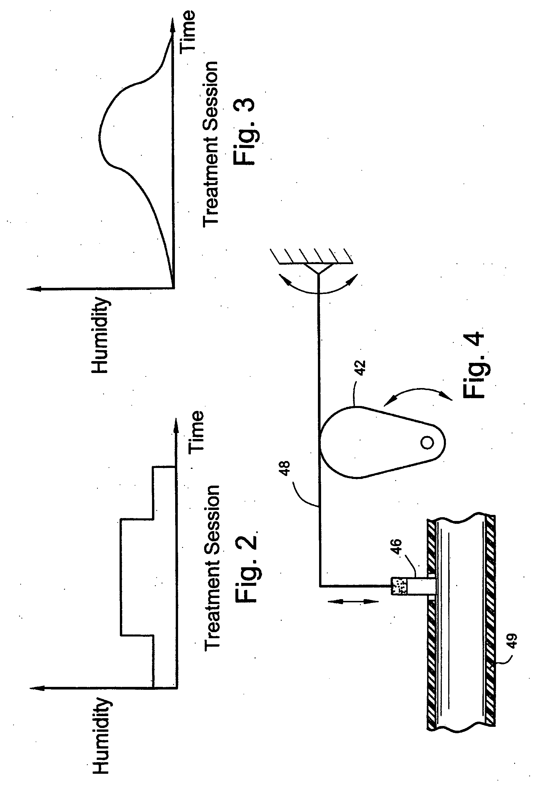
A method and apparatus for delivering breathable gas to a user includes a humidifying unit that is controllable to humidify the gas in accordance with a variable humidity profile such that the gas is delivered to the user at variable humidity levels, e.g., during a treatment session.

Description

CROSS-REFERENCE TO RELATED APPLICATIONS[0001]This application claims the benefit of U.S. Provisional Application No. 60 / 599,864, filed Aug. 10, 2004, incorporated herein by reference in its entirety.STATEMENT REGARDING FEDERALLY SPONSORED RESEARCH OR DEVELOPMENT[0002]None.BACKGROUND OF THE INVENTION[0003]Many humidifiers that are currently manufactured for patient respiratory disorders such as Obstructive Sleep Apnea (OSA) are large, bulky, and have large water reserves to treat most medical-related ailments such as dryness that may be caused by mouth leaks for example. Mouth leaks or any leaks for that matter release humidified gases to the atmosphere and bypasses the patient's airways where it is required. These heavy requirements including those medical conditions requiring high levels of continuous humidification may require humidifier devices with reserves as high as 600 mL of water. This increases the overall size and bulk of the Continuous Positive Airway Pressure (CPAP) Appa...

Claims


Application Information

Patent Timeline
IPC IPC(8): A61M16/16
CPCA61M16/16A61M16/0003A61M16/109A61M16/20A61M16/0051A61M16/0066A61M16/161A61M16/024
Inventor KWOK, PHILIP RODNEY
Owner RESMED LTD
Learn More