
Coexistence management for cooperative transceiving in a shared spectrum

Active Publication Date: 2008-12-04
AVAGO TECH INT SALES PTE LTD
View PDF8 Cites 46 Cited by
  • Summary
  • Abstract
  • Description
  • Claims
  • Application Information

AI Technical Summary

Problems solved by technology

Collision detection, as employed in Ethernet, cannot be used for the radio frequency transmissions of IEEE 802.11 devices.
Such an algorithm reduces the data rate for wireless communication when the number of unsuccessful attempts to transmit a packet reaches a certain threshold.
However, for the cases where transmission failed due to the interference from a WPAN transceiver collocated with the receiving node this rate adaptation algorithm would result in lowering the data rate, increasing the packet transmission time and thus further increasing the probability of the interference errors.
Lowering the rate increases the probability of losing packets due to congestion, thereby lowering performance.
When a packet is lost the overall network performance is affected.
Discarding directed frames might result in poor voice quality in a VoIP link or lower TCP throughput.
If a wireless station fails to receive non-unicast packets, it might result in the failure of protocols such as ARP and DHCP.
Losing beacon frames might result in loss of synchronization to the wireless network.
And while these two wireless systems use different technologies, they operate in the same 2.4 GHz ISM band, and as a result, can interfere with each other.
Such interference might cause degraded data throughput, reduced voice quality or even link disconnection.
The internal interference is much more severe as each wireless transceiver has drastic impact on the performance of the other, as it's transmit / receive activity may saturate the LNA of the other device.
The physical distance between WPAN and WLAN, the operating data rate, operating transmit power levels and amount of data all affect the interference.

Method used


Image

  • Coexistence management for cooperative transceiving in a shared spectrum
  • Coexistence management for cooperative transceiving in a shared spectrum
  • Coexistence management for cooperative transceiving in a shared spectrum

Examples


Embodiment Construction

[0032]The following abbreviations are presented for clarity:

A2DPAdvanced Audio Distribution ProfileAPAccess PointACKAcknowledgementACLAsynchronous ConnectionlessAFHAdaptive Frequency HoppingBTBluetoothBSSBasic Service SetCRCCyclic Redundancy CheckCSMA / CACarrier Sense Multiple Access withCollision AvoidanceCTSClear To SendDCFDistributed Coordination FunctioneSCOEnhanced Synchronous Connection OrientedFHSSFrequency Hopping Spread SpectrumISMIndustrial, Scientific and MedicalLNALow Noise AmplifierMACMedium Access ControlNAVNetwork Allocation VectorPAPower AmplifierPCFPoint Coordination FunctionPHYPhysical layerPTAPacket Transmit ArbitrationRTSRequest To SendRXReceiveSCOSynchronous Connection OrientedSTAStationTDDTime-Division DuplexTSFTiming Synchronization FunctionTXTransmitUMAUnlicensed Mobile AccessVoIPVoice over IPWLANWireless Local Area NetworkWPANWireless Personal Area Network

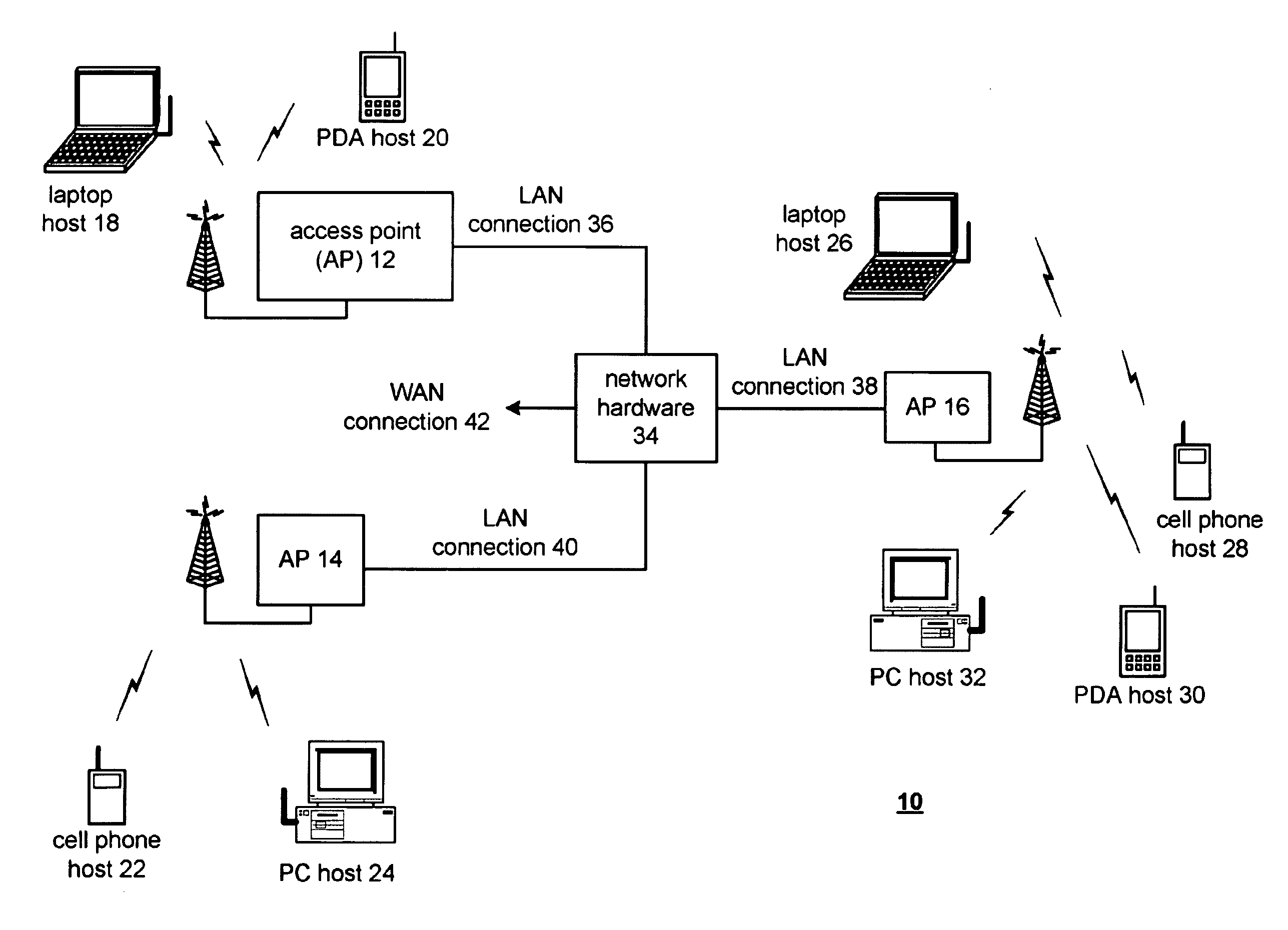
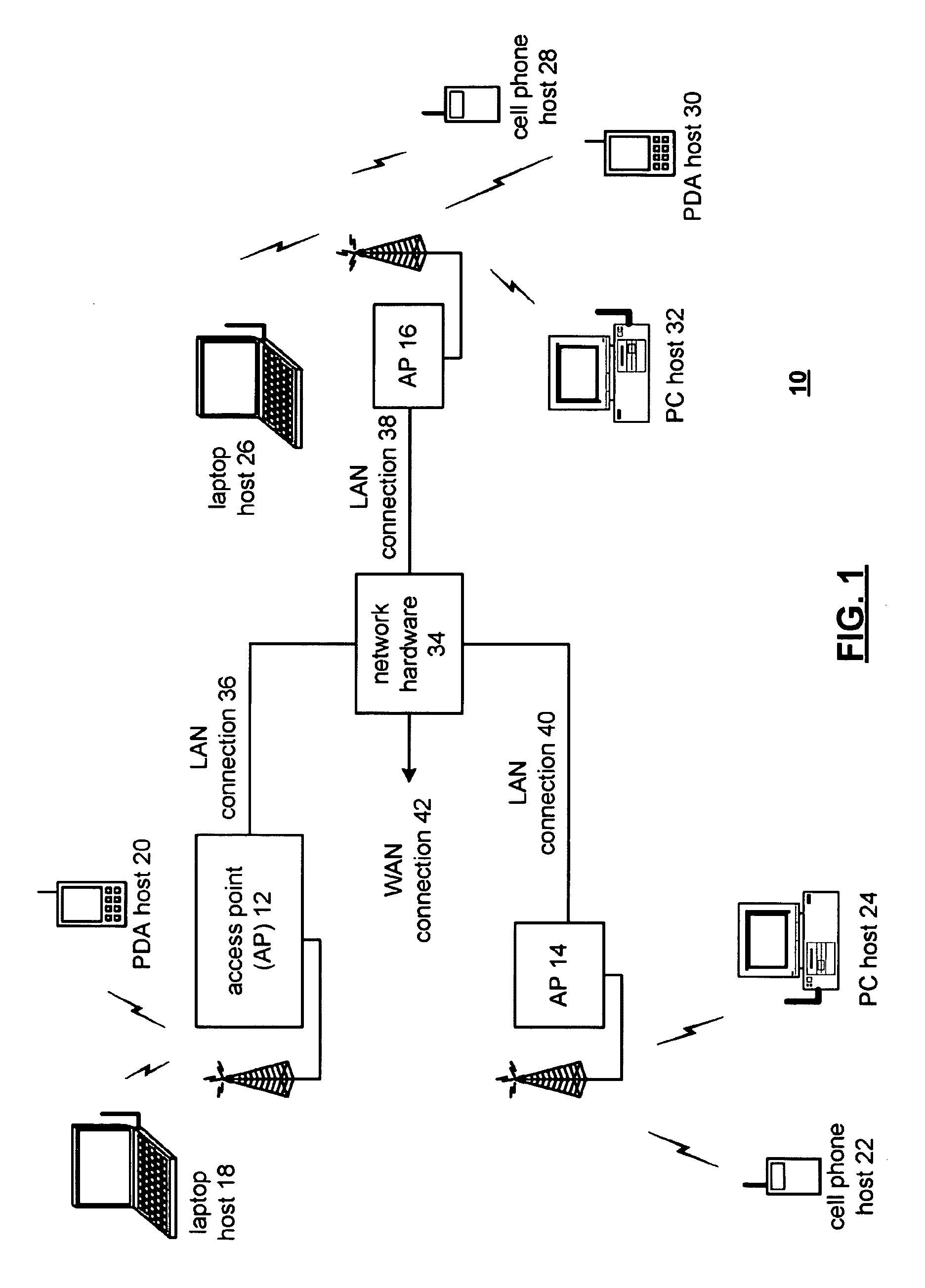
[0033]FIG. 1 is a schematic block diagram illustrating a communication system 10 that includes a pluralit...


PUM


Abstract

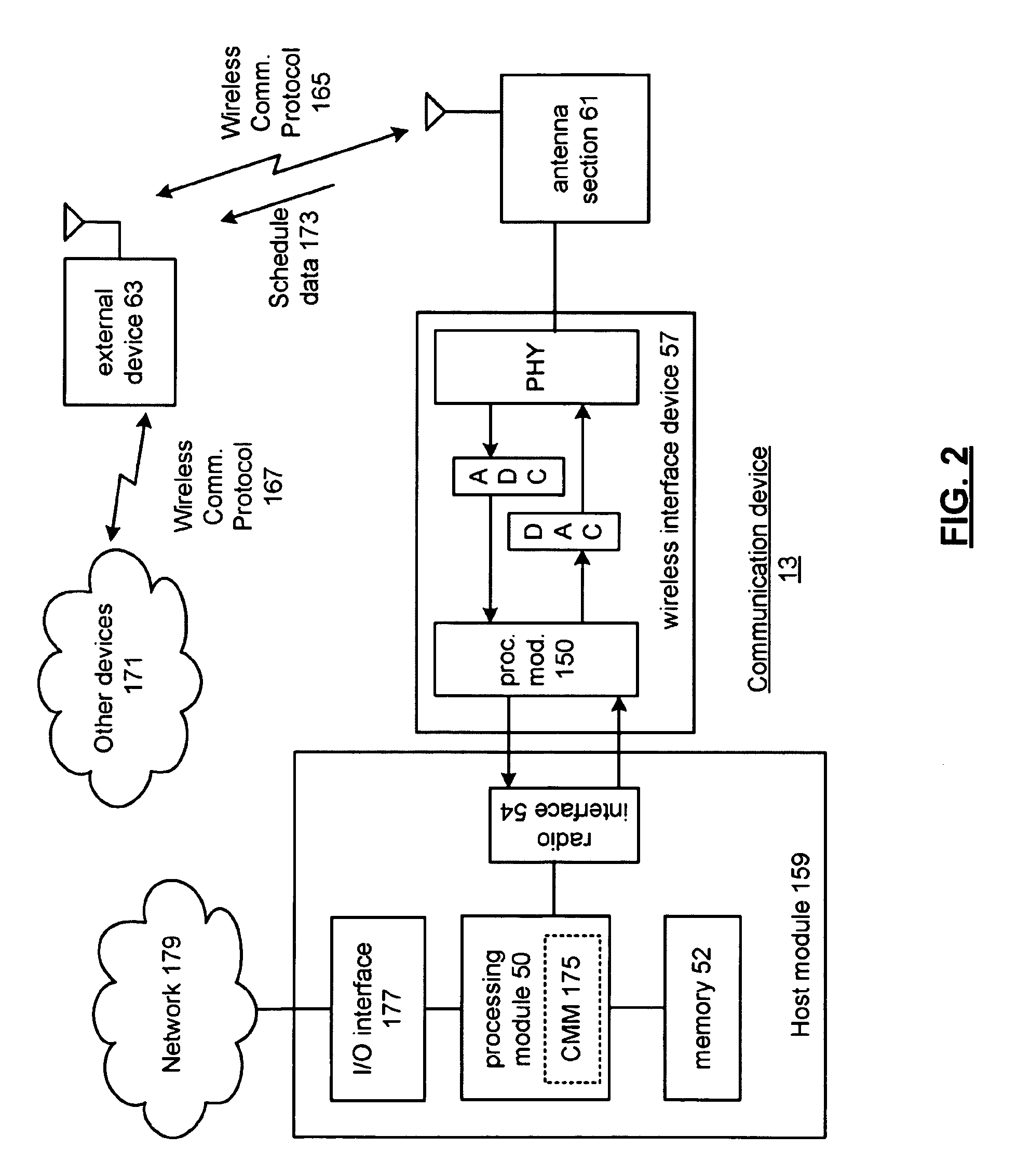
A wireless interface circuit transceives packetized data between a host module and a first external device using a frequency spectrum, wherein the packetized data is formatted in accordance with a first wireless communication protocol and wherein the packetized data includes a request from the first external device to use at least a potion of the frequency spectrum for communication via a second wireless communication protocol. A coexistence management module generates a wireless interface schedule that includes a least one contention free period reserved for communication via the second wireless communication protocol, and generates schedule data, based on the wireless interface schedule, for transmission to a plurality of external devices including the first external device.

Description

CROSS-REFERENCE TO RELATED APPLICATIONS[0001]The present application claims priority under 35 U.S.C. 119 to provisionally filed application Ser. No. 60 / 932,852, entitled, “COEXISTENCE MANAGEMENT FOR COOPERATIVE TRANSCEIVING IN A SHARED SPECTRUM,” filed on May 31, 2007.BACKGROUND OF THE INVENTION[0002]1. Technical Field of the Invention[0003]This invention relates generally to wireless communication systems and more particularly to cooperative transceiving by wireless interface devices of the same host device.[0004]2. Description of Related Art[0005]Communication systems are known to support wireless and wire lined communications between wireless and / or wire lined communication devices. Such communication systems range from national and / or international cellular telephone systems to the Internet to point-to-point in-home wireless networks. Each type of communication system is constructed, and hence operates, in accordance with one or more communication standards. For instance, wirele...

Claims


Application Information

Patent Timeline
IPC IPC(8): H04Q7/20H04W16/10H04W92/02
CPCH04W16/10H04W92/02
Inventor IYER, MAHESHHAYES, RAYMOND R.
Owner AVAGO TECH INT SALES PTE LTD
Learn More