Eureka AIR delivers breakthrough ideas for toughest innovation challenges, trusted by R&D personnel around the world.

Fluid Bed Granulation Process

a technology of fluid bed and granulation process, which is applied in the direction of liquid spraying apparatus, chemical equipment and processes, coatings, etc., can solve the problems of high operating cost, inability to control the particle size of finished products within a predetermined range of values, and inability to achieve adequate, satisfactory control of the growth of granules inside the fluid bed, so as to improve the cost-effectiveness of the process, reduce the formation of powder and clots, and tighten the control of granulation steps

Inactive Publication Date: 2008-12-04
CASALE SA
View PDF100 Cites 7 Cited by
  • Summary
  • Abstract
  • Description
  • Claims
  • Application Information

AI Technical Summary

Benefits of technology

[0017]The problem underlying the present invention is that of devising and providing a fluid bed granulation process having functional characteristics so as to overcome all the cited drawbacks with reference to the prior art, i.e. which allows a tighter control of the granulation steps, a substantial reduction in the formation of powders and clots and, last but not least, a considerable improved cost-effectiveness of the process.

Problems solved by technology

Although they are advantageous from various points of view, fluid bed granulation processes of the prior art suffer from recognized drawbacks, including the substantial impossibility of controlling the particle size of the finished product within a predetermined range of values and the high operating costs.
Indeed, the atomization of said growth fluid is generally obtained with large amounts of high-speed air and this notoriously prevents an adequate, satisfactory control of the growth of the granules inside the fluid bed.
Moreover, as a consequence of the aforementioned drawback, it is necessary to make use of classification and screening operations of the granules produced, to take care of the discarding, always considerable, of the granules of unacceptable size (either too big or too small), and of recovery operations of such discard and its recycling upstream of the granulation process.
Other recognized drawbacks of fluid bed granulation processes of the prior art consist of the non-optimal uniform wetting of the seeds and of the granules of substance in growth, as well as the undesired formation of clots, with the consequent considerable reduction in yield of the entire process.

Method used


Image

  • Fluid Bed Granulation Process
  • Fluid Bed Granulation Process
  • Fluid Bed Granulation Process

Examples


Embodiment Construction

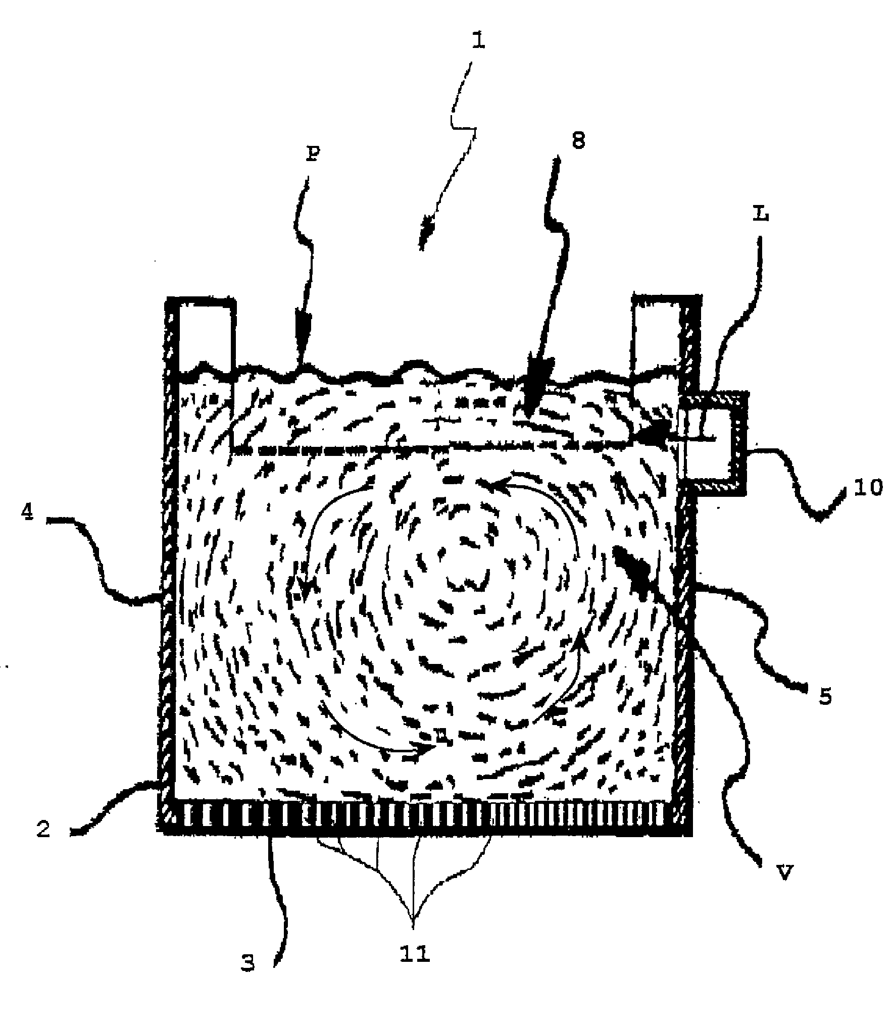
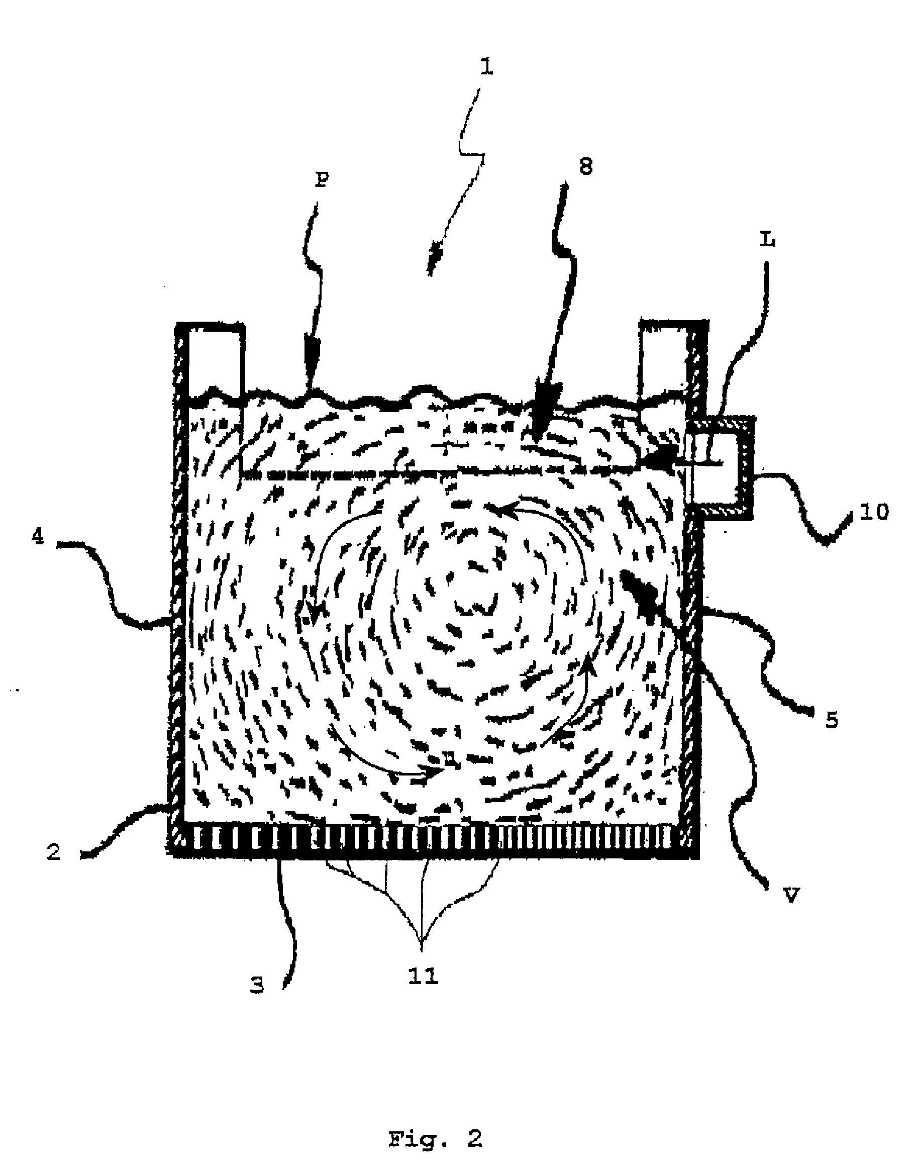
[0032]With reference to FIGS. 1, 2, 3, 3a an apparatus for carrying out a fluid bed granulation process according to the present invention is globally indicated with 1, an apparatus that in the rest of the description shall be more simply called granulator.

[0033]In an entirely schematic way, said granulator 1 comprises a container 2, represented open at the top, that is substantially parallelepiped in shape, with a rectangular section.

[0034]Said container 2 has a bottom 3, permeable to gas, consisting of a perforated element (grid), two opposite long side walls 4, 5 and two opposite short walls, front 6 or head and rear 7.

[0035]At the upper side of the head wall 6 a device, schematized as 9, per se conventional and therefore not described in detail, is supported for supplying a continuous flow of seeds S1 of substance to be granulated into the container 2. In the rear wall 7 and at a predetermined height over the bottom or grid 3, an opening 8 is formed, for the discharge, substanti...


PUM

PropertyMeasurementUnit
Flow rateaaaaaaaaaa
Diameteraaaaaaaaaa
Densityaaaaaaaaaa

Abstract

A fluid bed granulation process of a predetermined substance comprises the steps of: forming, through a fluidification. air flow of predetermined flow rate, a fluid bed of granules of said substance to be granulated fed to it in the form of seeds, —feeding said fluid bed with a continuous flow of a growth substance (or liquid).

Description

FIELD OF APPLICATION[0001]In its most general aspect, the present invention refers to a fluid bed granulation process of a suitable substance like, for (not limiting) example, urea, ammonium nitrate, ammonium chloride and similar substances susceptible to being granulated.[0002]More specifically, this invention concerns a fluid bed granulation process in which the obtainment of granules of a predetermined substance occurs through continuous growth (of volume and of mass), of granule seeds of such a substance, fed continuously into said fluid bed, at the same time with a flow of an appropriate growth substance in liquid state.[0003]In the rest of the description and in the subsequent claims, with the terms “granule seeds of a predetermined substance”, we intend to indicate particles of the substance to be granulated, having a size of up to about 2.5 mm. Moreover, for the sake of simplification, we shall just use the term “seeds” to indicate granule seeds.[0004]The invention also refe...

Claims


Application Information

Patent Timeline
IPC IPC(8): B05D7/00B05C5/00B01J2/16B01J8/44
CPCB01J2/16B05C19/06B05C19/02
Inventor BEDETTI, GIANFRANCO
Owner CASALE SA
Why Eureka
Eureka Blog
Learn More