
Automated real speech hearing instrument adjustment system

Inactive Publication Date: 2008-12-04
POE MICHAEL +3
View PDF0 Cites 97 Cited by
  • Summary
  • Abstract
  • Description
  • Claims
  • Application Information

AI Technical Summary

Benefits of technology

[0003]In regards to the human auditory system, hearing aid devices (“hearing instruments”) are often used to compensate for hearing loss. The primary function of hearing instruments is to amplify the incoming signal in a manner appropriate to make the signal audible to the user. The amount of signal amplification may differ at various frequencies, normally audible to the human ear, based upon the degree of hearing loss at each frequency. Another important function of a hearing instrument is to limit the amplification of the incoming sound to a level that is not intolerable or uncomfortable to the user of the instrument.
[0008]More recently, analyzing tools have been developed that utilize recorded or live speech as the input signal, such as the MedRx Avant™ REM Speech System. These devices provide the dispenser a better understanding of the audibility and comfort of important amplified speech signals.

Problems solved by technology

In addition, the measured insertion response may not match the target response.
Because the adjustments are made manually, they are time consuming and therefore can contribute to the cost of a hearing aid device and possibly decrease the amount of time the dispenser has available to counsel the hearing instrument user about the care and use of the instrument.
If the dispenser lacks sufficient experience, the adjustments may not be completed properly.
As a result, the hearing instrument user might not receive the full benefit from the use of the device and / or may refuse to wear the instrument.

Method used


Image

  • Automated real speech hearing instrument adjustment system
  • Automated real speech hearing instrument adjustment system
  • Automated real speech hearing instrument adjustment system

Examples


Embodiment Construction

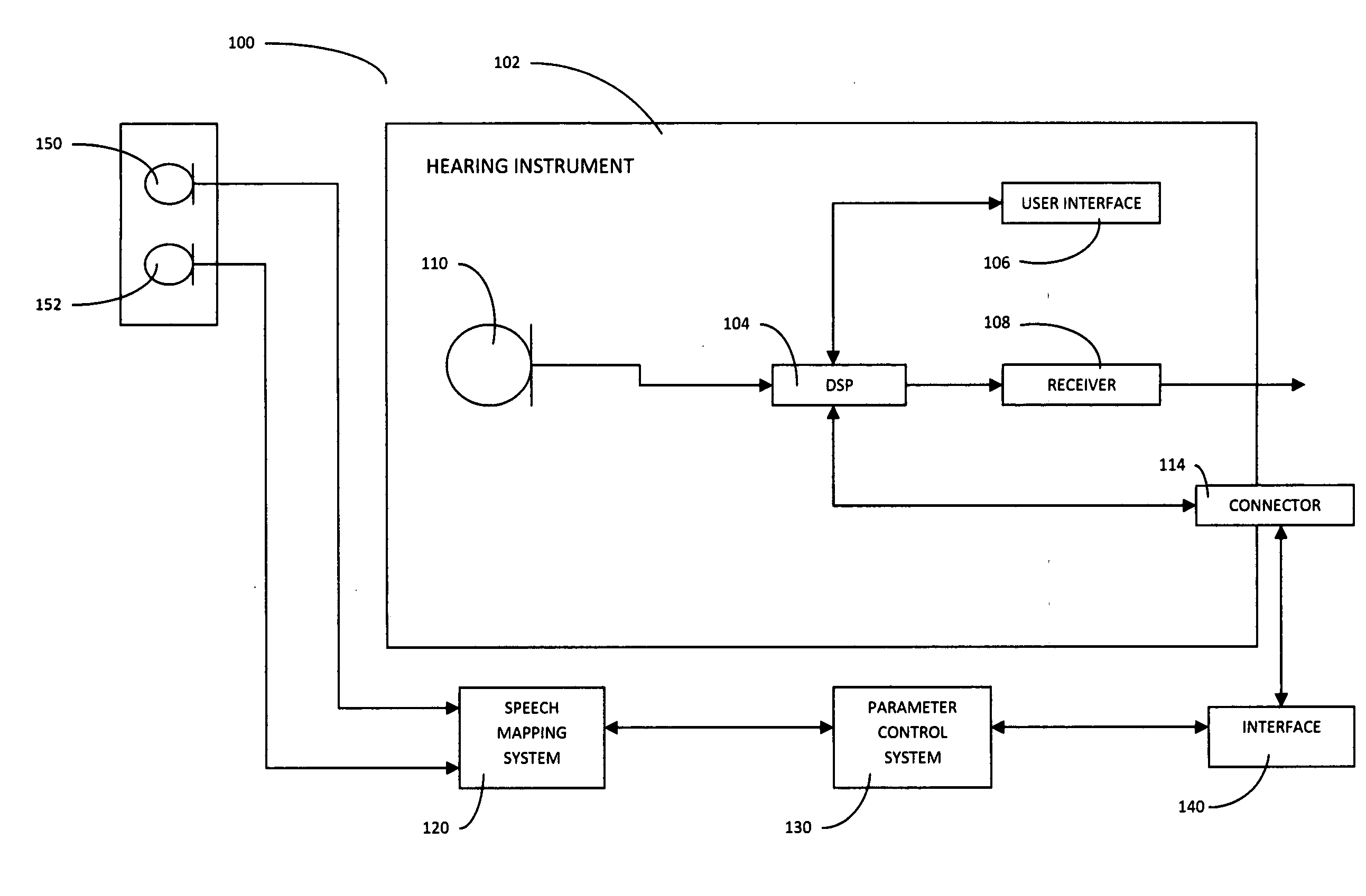
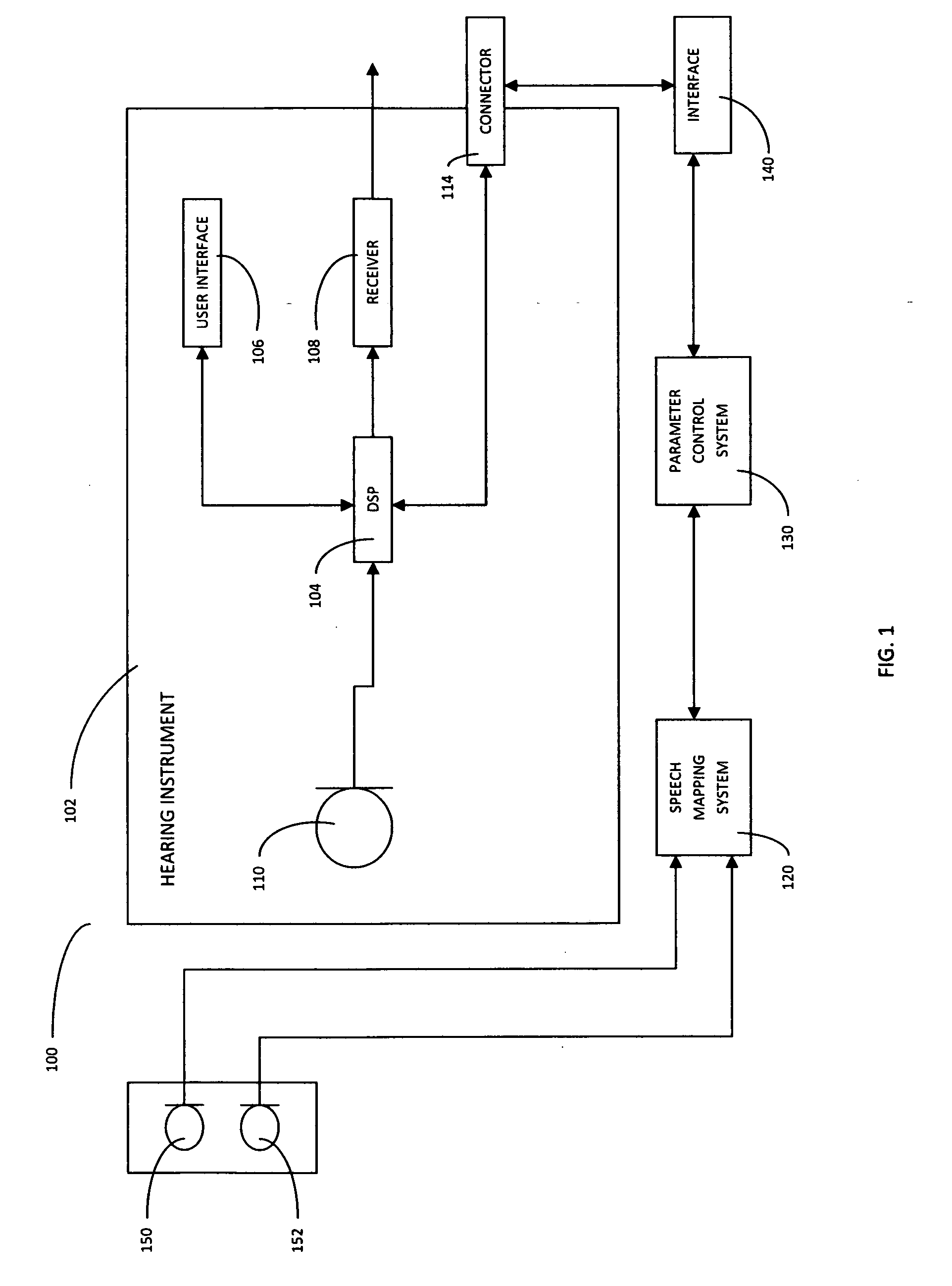
[0027]A system and method that automatically adjust the parameters of a digital, programmable hearing instrument utilizing information derived from the results of speech mapping are presented. As used herein “speech” (unless specifically indicated otherwise) refers to live speech, pre-recorded speech signals, speech and noise signals, music signals and / or speech-like stimuli, calibrated stimuli, pure tones, random speech noise or other complex audio signals.

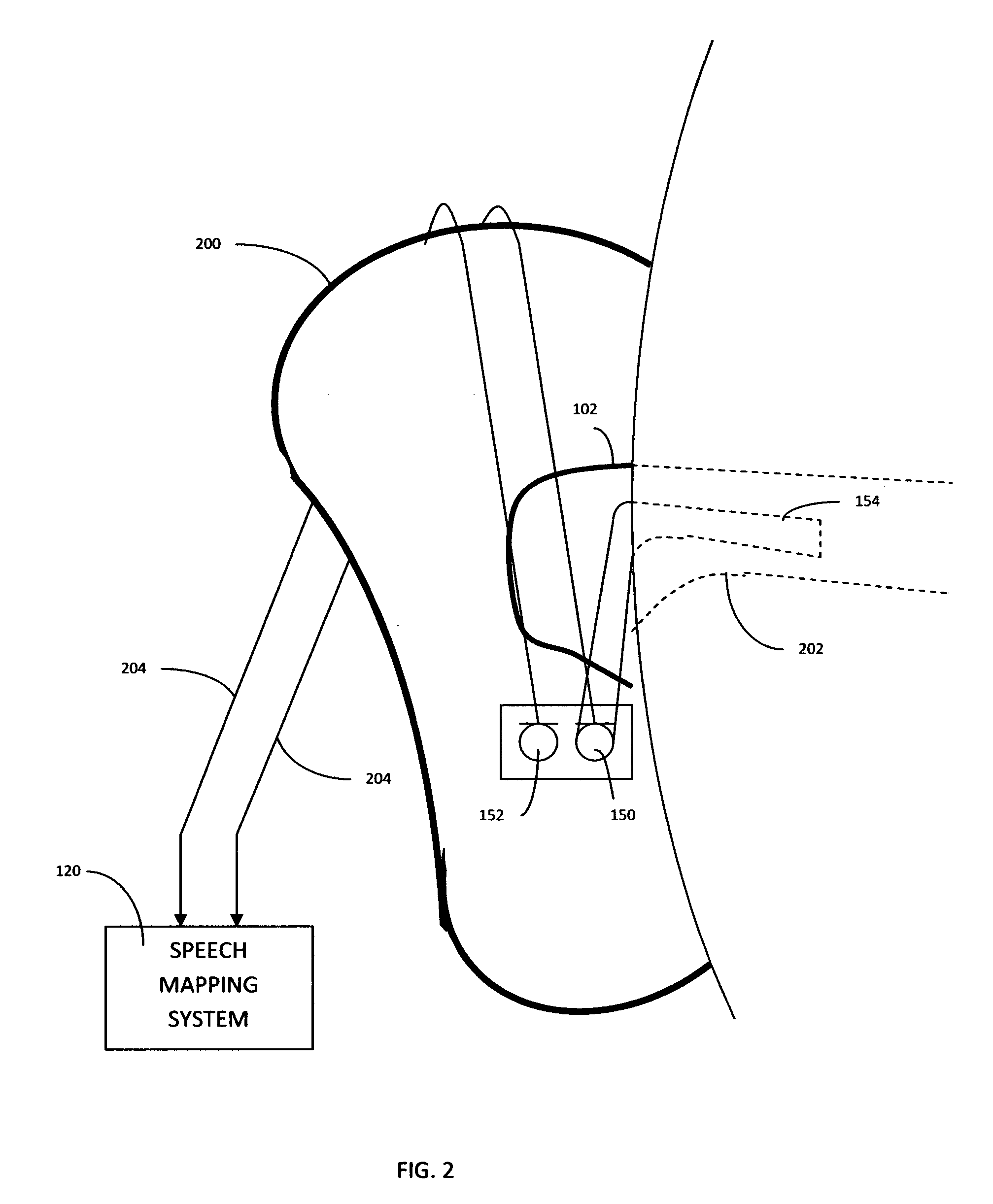
[0028]In one embodiment of the disclosed system and method, the dispenser or fitter of the hearing instrument obtains information through the use of a speech mapping system. The information obtained from the use of the speech mapping system is specific to the performance of the hearing instrument, the resonance of the user's external auditory canal and pinna, and the instrument user's hearing loss. Embodiments of the disclosed system and method utilize the hearing instrument manufacturer's fitting software and the information obt...


PUM


Abstract

A method for fitting a hearing instrument comprises placing the hearing instrument in situ includes receiving an audiogram of the user, determining a target gain for the hearing instrument as a function of the audiogram, exposing a reference sensor located adjacent the hearing instrument to an external speech signal, measuring an external sound pressure level (SPL) via the reference sensor, exposing a probe sensor coupled to the inside of the ear to the output of the hearing instrument while the hearing instrument is in situ, measuring an internal sound pressure level (“SPL”) inside the ear of the user via the probe sensor, determining an offset gain as a function of the external SPL, the target gain and the internal SPL, and automatically adjusting a gain of the hearing instrument according to the offset gain. A system for automatically fitting a hearing impaired person with a digital hearing aid in situ includes a digital hearing aid, a reference volume sensor, a probe sensor, a sound mapping module and a parameter control module.

Description

[0001]This application claims priority to U.S. Provisional application 60 / 925,623 filed Apr. 19, 2007 the disclosure of which is incorporated herein by this reference.BACKGROUND AND SUMMARY[0002]This disclosure relates to systems and methods of fitting hearing devices and more particularly to systems and methods of fitting hearing devices wherein measurements of the output of the hearing device are taken within the ear of the intended wearer of the hearing device.[0003]In regards to the human auditory system, hearing aid devices (“hearing instruments”) are often used to compensate for hearing loss. The primary function of hearing instruments is to amplify the incoming signal in a manner appropriate to make the signal audible to the user. The amount of signal amplification may differ at various frequencies, normally audible to the human ear, based upon the degree of hearing loss at each frequency. Another important function of a hearing instrument is to limit the amplification of the...

Claims


Application Information

Patent Timeline
IPC IPC(8): H04R29/00
CPCH04R25/70
Inventor POE, MICHAELQUICK, ANTHONYCHARI, SRINIVASCAMPBELL, DON E.K.
Owner POE MICHAEL
Learn More