
Devices, Systems and Methods for Determining Sizes of Vessels

a technology of vessels and devices, applied in the field of medical diagnostics and treatment, can solve the problems of inability to disclose a technique for determining the size of vessels, affecting the conductivity of measurement fields, and preventing accurate measurements, so as to achieve easy reproducibility and minimal invasive

Inactive Publication Date: 2008-11-27
DTHERAPEUTICS
View PDF36 Cites 86 Cited by
  • Summary
  • Abstract
  • Description
  • Claims
  • Application Information

AI Technical Summary

Benefits of technology

[0007]The present invention provides devices, systems and methods for determining the size of a blood vessel. The term “vessel,” as used herein, refers generally to any hollow, tubular, or luminal organ. Techniques according to the present invention are minimally invasive, accurate, reliable and easily reproducible.
[0009]In one exemplary embodiment, the present invention is a device for determining a cross sectional size of a vessel. The device includes an elongated body having a longitudinal axis extending from a proximal end to a distal end, the body having a lumen along the longitudinal axis and enabling introduction of the distal end into a lumen of a vessel; a first excitation electrode and a second excitation electrode along the longitudinal axis, both located in respective grooves near the distal end; and a first detection electrode and a second detection electrode located in respective grooves along the longitudinal axis and in between the first and second excitation electrodes; wherein at least one of the first and second excitation electrodes is in communication with a current source, thereby enabling a supply of electrical current to the vessel, thereby enabling measurement of two or more conductance values in the blood vessel by the detection electrodes, and thereby enabling calculation of parallel tissue conductance in the vessel, whereby tissue conductance is the inverse of resistance to current flow, which depends on the cross sectional area of the blood vessel.
[0010]In another exemplary embodiment, the present invention is a device for determining a cross sectional area of a vessel. The device includes an elongated body having a lumen therethrough along its longitudinal length; a pair of excitation electrodes located in respective grooves on the elongated body; and a pair of detection electrodes located in respective grooves located in between the pair of excitation electrodes such that a distance between one detection electrode and its adjacent excitation electrode is equal to the distance between the other detection electrode and its adjacent excitation electrode; wherein at least one excitation electrode is in communication with a current source, thereby enabling a supply of electrical current to a lumen of a vessel, and enabling measurement of two or more conductance values at the lumen by the detection electrodes, resulting in an assessment of the cross sectional area of the blood vessel.
[0013]In another exemplary embodiment, the present invention is a catheter system for determining a cross sectional area of a vessel as determined by resistance to flow of electrical currents through the lumen. The system includes an elongate wire having a longitudinal axis with a proximal end and a distal end; a catheter comprising an elongate tube extending from a proximal tube end to a distal tube end, the tube having a lumen and surrounding the wire coaxially; a first excitation electrode and a second excitation electrode each located in respective grooves along the longitudinal axis of the wire near the distal wire end; and a first detection electrode and a second detection electrode in respective grooves along the longitudinal axis of the wire and in between the first and second excitation electrodes, wherein at least one of the first and second excitation electrodes is in communication with a current source, thereby enabling a supply of electrical current to a lumen of a vessel, thereby enabling measurement of two or more conductance values at the lumen by the detection electrodes, and thereby enabling calculation of tissue conductance at the lumen, whereby tissue conductance is the inverse of resistance to current flow, which depends on the cross sectional area of the vessel.

Problems solved by technology

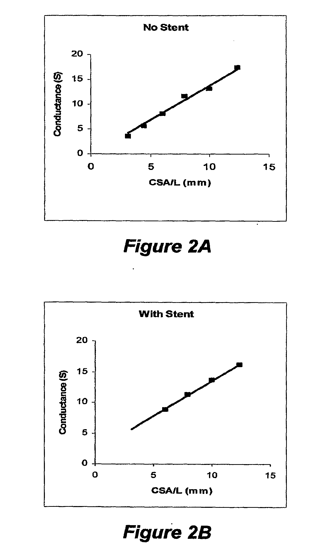
The previous devices, systems and methods did not disclose a technique of determining vessel size in the presence of a stent (typically a metal).
In using prior embodiments, it is noted that contact of the impedance electrodes with the stent causes electrical shorting of signal and significant resulting noise, which prohibits accurate measurements.
Furthermore, the presence of a metal in the measurement field also affects the conductivity.

Method used


Image

  • Devices, Systems and Methods for Determining Sizes of Vessels
  • Devices, Systems and Methods for Determining Sizes of Vessels
  • Devices, Systems and Methods for Determining Sizes of Vessels

Examples


Embodiment Construction

[0019]This invention makes easy, accurate and reproducible measurements of the size of blood vessels within acceptable limits. This enables the determination of a blood vessel size with higher accuracy using basic techniques previously presented in more detail in the prior parent applications.

[0020]An exemplary embodiment of the present invention is presented as device 100 in FIG. 1. In this figure, a portion of a catheter 101 is presented at three different magnifications 110, 120 and 130. This catheter 101 has multiple electrodes 111, 112, 113 and 114 at one end. Such electrodes are used as described in the prior applications from which the present applications claims priority to. Thus, they will not be described in detail here. In brief, the two outer electrodes 111 and 114 are the excitation electrodes and the two inner electrodes 112 and 113 are the detection electrodes.

[0021]A further magnification 130 of the area around one of the electrodes 114 is presented. Multiple grooves...


PUM


Abstract

Devices, systems and methods are disclosed for determining the cross sectional area of a vessel. Through a combination of fluid injection with different conductivities and measurement of the resultant conductances, parallel tissue conductance measure is obtained that assists in determining the cross sectional area, taking into account the presence of a stent.

Description

[0001]This patent application claims priority to U.S. Provisional Patent Application Ser. No. 60 / 761,783, filed Jan. 25, 2006; and is a continuation-in-part of U.S. patent application Ser. No. 11 / 063,836, filed Feb. 23, 2005, which is a continuation-in-part of U.S. patent application Ser. No. 10 / 782,149, filed Feb. 19, 2004; which claims priority to U.S. Provisional Patent Application Ser. No. 60 / 449,266, filed Feb. 21, 2003, and to U.S. Provisional Patent Application Ser. No. 60 / 493,145, filed Aug. 7, 2003, and to U.S. Provisional Patent Application Ser. No. 60 / 502,139, filed Sep. 11, 2003, the contents of each of which are hereby incorporated by reference in their entirety into this disclosure.BACKGROUND OF THE INVENTION[0002]1. Field of the Invention[0003]The present invention relates generally to medical diagnostics and treatment. More particularly, the present invention relates to devices, systems and methods for determining size of vessels, particularly in the presence of a st...

Claims


Application Information

Patent Timeline
Patent Type & Authority Applications(United States)
IPC IPC(8): A61B5/053A61B6/00
CPCA61B5/02007A61B5/053A61B5/0538A61B5/1076
Inventor KASSAB, GHASSAN S.
Owner DTHERAPEUTICS
Learn More