3-d optical microscope
a three-dimensional, optical microscope technology, applied in the field of optical microscopes, can solve the problems of inability to quantitatively measure the depth dimension, difficult to maintain and operate, and expensive construction of conventional microscopes, and achieve the effect of reliable and accurate 3-d imaging and low cos
- Summary
- Abstract
- Description
- Claims
- Application Information
AI Technical Summary
Benefits of technology
Problems solved by technology
Method used
Image
Examples
first embodiment
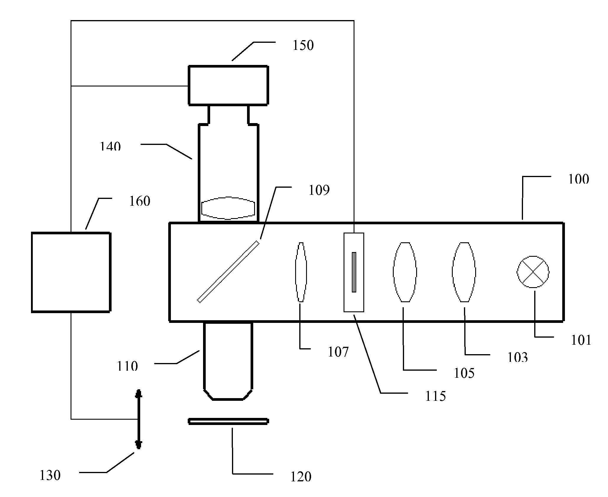
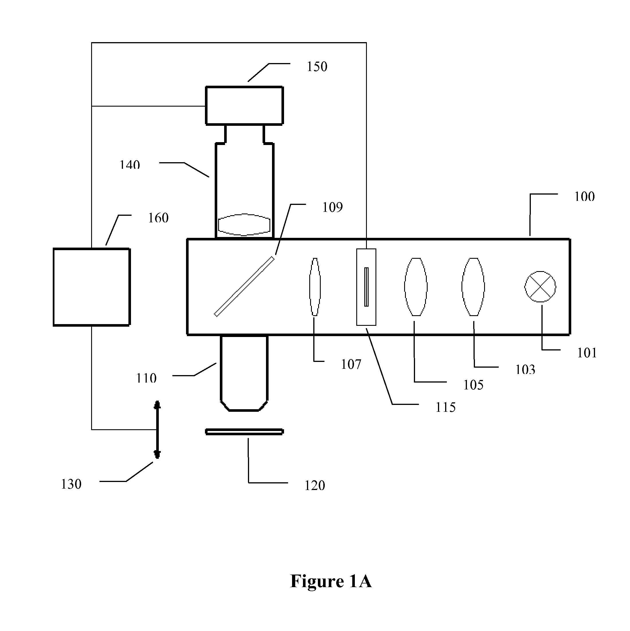
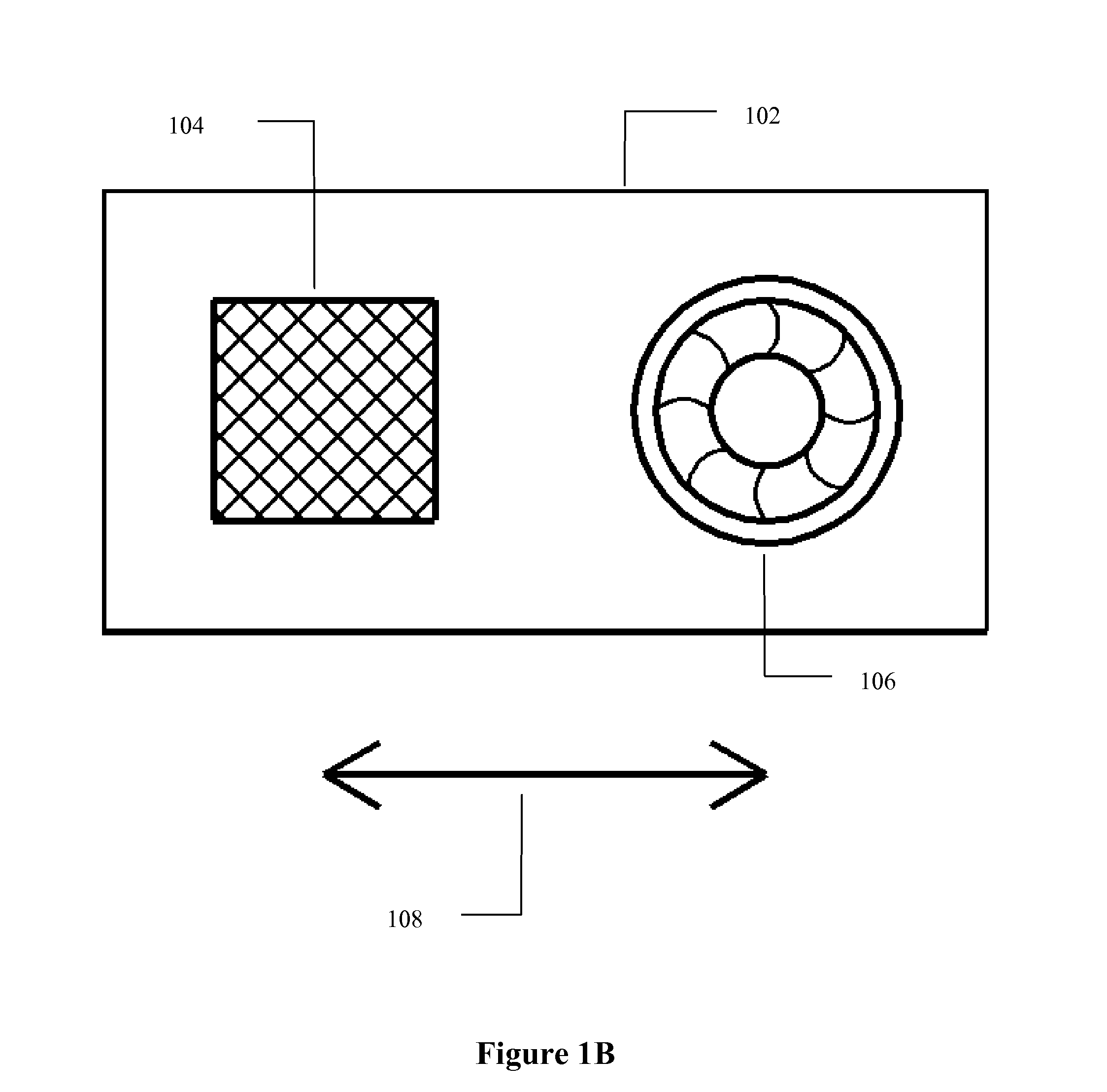
[0032]FIG. 1A is a diagram illustrating a 3-D optical microscope with a reflective illuminator in accordance with the present invention. A microscope operating in reflective illumination mode is often used for studying opaque samples such as a semiconductor wafer. Reflective illuminator 100 provides illumination for the microscope and contains several components. Light source 101 generates illuminating light. Among possible choices for the light source are: a lamp, a fiber coupled light, a LED light, a laser, and etc. In the preferred embodiment, either a halogen lamp or a fiber coupled light source is used. Lenses 103, 105, and 107 ensure uniform illumination on sample 120 and, when pattern generator 115 is placed in the illuminator optical path, project an image of a patterned article to the focal plane of objective lens 110. Beam-splitter 109 is mounted at a 45° angle with respect to a centerline connecting lenses 103, 105, and 107 so that light from the light source is directed ...
third embodiment
[0069]the present invention, shown in FIG. 7, is a 3-D optical microscope with a transmitted illuminator. A microscope operating in transmitted illumination mode is often used for studying transparent objects such as biology related samples. Transmitted illuminator 700 provides illumination for the microscope and contains several components. Light source 701 generates illuminating light. Among possible choices for the light source are: a lamp, a fiber coupled light, a LED light, a laser, and etc. In the preferred embodiment, either a halogen lamp or a fiber coupled light source is used. Lenses 703, 705, 707, and 711 ensure uniform illumination on sample 720 and, when pattern generator 115 is placed in the illuminator optical path, project an image of the patterned article to the focal plane of objective lens 710. Beam-splitter 709 is mounted at a 45° angle with respect to a centerline connecting lenses 703 and 705 so that light from the light source is directed vertically upward to ...
fifth embodiment
[0075]FIG. 9B illustrates modifications made to a conventional microscope of FIG. 9A in order to turn it into a 3-D optical microscope in accordance with the present invention. F-stop 902 of FIG. 9A is replaced by pattern generator 115 of FIG. 1A. Means for focusing adjustment 913 is implemented either on fine focus knob 909 or on objective turret 903 of FIG. 9A. Some examples of means for focusing adjustment are electrical motor, piezoelectric actuator, and etc. In the preferred embodiment, means for focusing adjustment 913 is a motor coupled to fine focus knob 909 of FIG. 9A. It is understood that other means of focusing adjustment is also within the scope of the present invention. Coupler 914 is mounted on trinocular tube 911 and camera 915 is attached to coupler 914. Finally, processor 160 is connected to the modified microscope of FIG. 9B. The processor is used to control means for focusing adjustment 913, camera 915, and pattern generator 115. In addition, said processor analy...
PUM
 Abstract
Description
Claims
Application Information
 - R&D
- Intellectual Property
- Life Sciences
- Materials
- Tech Scout
- Unparalleled Data Quality
- Higher Quality Content
- 60% Fewer Hallucinations
Browse by: Latest US Patents, China's latest patents, Technical Efficacy Thesaurus, Application Domain, Technology Topic, Popular Technical Reports.
© 2025 PatSnap. All rights reserved.Legal|Privacy policy|Modern Slavery Act Transparency Statement|Sitemap|About US| Contact US: help@patsnap.com


