
Space-Dividing Apparatus

a technology of space-dividing apparatus and dividing screen, which is applied in the field of space-dividing screen, can solve the problems of low degree of freedom in changing the image to be displayed, inconvenient for users, and troublesome users

Inactive Publication Date: 2008-11-27
SONY CORP
View PDF6 Cites 7 Cited by
  • Summary
  • Abstract
  • Description
  • Claims
  • Application Information

AI Technical Summary

Benefits of technology

[0008]It is an object of the present invention to provide a space-dividing apparatus that enables a user to easily observe, for example, the other side of a single-leaf screen. It is another object of the present invention to provide a space-dividing apparatus that enables to be separately used with ease any image display elements mounted to, for example, a single-leaf screen.

Problems solved by technology

Accordingly, for example, if a user would like to look at the other side of the partition, for example, out of a window, as in the case of a partition not provided with an information display device, this partition provided with the information display device requires the user himself to move to a position where the partition will not block his or her view, thus being greatly troublesome for the user.
In this case, to use the information display device in condition where it is separated from the partition, the mounting panel to which the information display device is mounted is detached, in which case the information display device would be carried around in condition where it is mounted to the mounting panel, thus inconveniencing the user greatly.
This display section in the display-attached furniture piece does not display an image by using a video signal and also has a low degree of freedom in changing an image to be displayed.
Further, in this display-attached furniture piece, the display section is added to such a portion of a furniture piece as not to obstruct original use thereof, for example, a back side thereof, so that functions of the furniture piece are not greatly upgraded.

Method used


Image

  • Space-Dividing Apparatus
  • Space-Dividing Apparatus
  • Space-Dividing Apparatus

Examples


Embodiment Construction

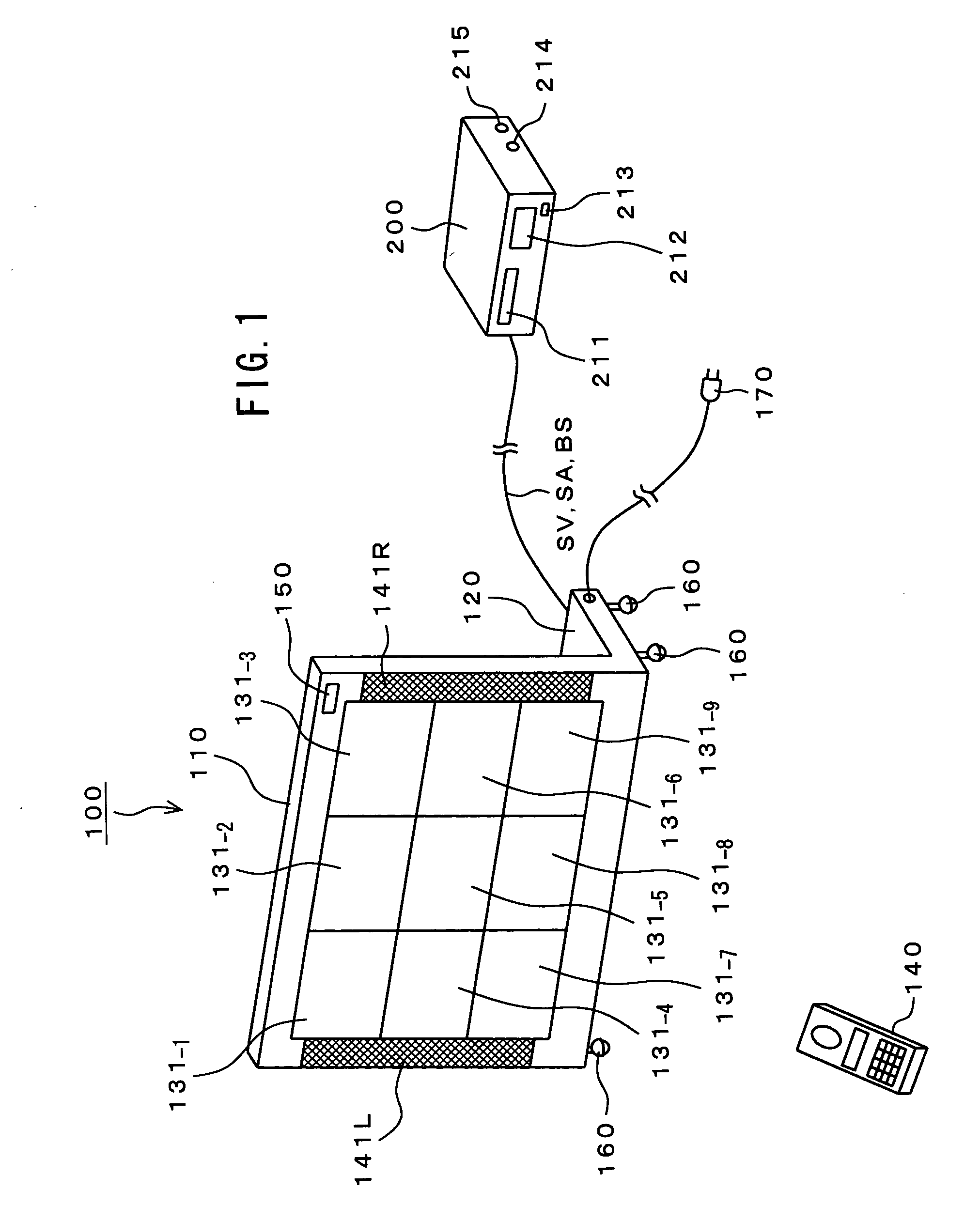
[0092]Embodiments of the present invention will be described below. FIG. 1 shows a configuration of a single-leaf screen device 100 according to the embodiment.

[0093]This single-leaf screen device 100 has a rectangular division plate section 110 that divides a space. This division plate section 110 is connected to a rectangular base section 120 with it being erected upright at a latitudinal end of this base section 120.

[0094]At a midsection of this division plate section 110 on a front surface side thereof, nine TV receiving sets 131-1 through 131-9 are arranged in an attachable / detachable manner in a 3-by-3 matrix shape. These TV receiving sets 131-1 through 131-9 each constitute an image display element. These TV receiving sets 131-1 through 131-9 each have a flat panel display such as a liquid crystal display (LCD) and a plasma display panel (PDP).

[0095]Further, a left-side speaker 141L is arranged at a left end of this division plate section 110 on the front surface side thereof...


PUM


Abstract

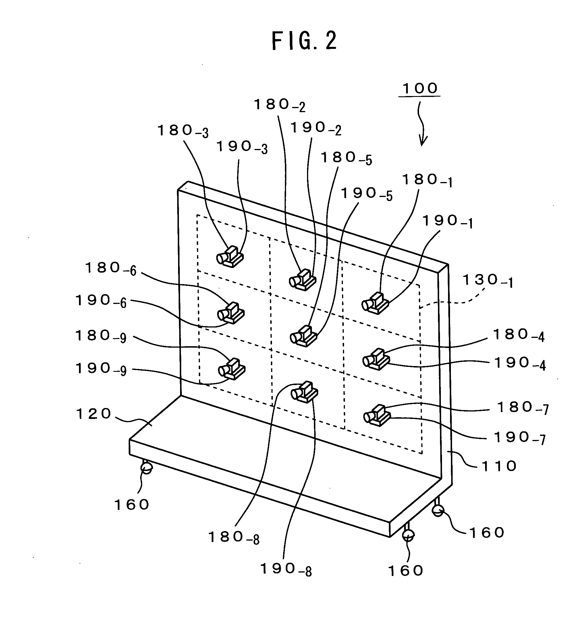
The present invention relates to a space-diving apparatus that could well be preferably applied to a single-leaf section, a divider etc. A division plate section 110 constitutes a single-leaf screen device 100 and divides a space. On a front surface of the division plate section 110, nine TV receiving sets 131-1 through 131-9 are arranged in a matrix shape and an attachable / detachable manner. These TV receiving sets 131-1 through 131-9 can be detached and individually used. If the TV receiving set is detached, a decorative sheet is arranged to a position where this receiving set has been arranged. On a back surface of the division plate section 110, nine image pickup elements are mounted to, for example, positions that correspond to the TV receiving sets 131-1 through 131-9, respectively. An imaging direction of each of the image pickup elements can be automatically aligned with a line of sight of the user based on a position of the user (position of a remote controller). An image due to a video signal obtained by each of the image pickup elements can be displayed on the TV receiving sets 131-1 through 131-9, thereby permitting the user to observe the other side of the division plate section 110 easily.

Description

TECHNICAL FIELD[0001]The present invention relates to a space-dividing apparatus that could well be applied to, for example, a single-leaf screen, a divider, etc. More specifically, the present invention relates to a space-dividing apparatus in which image display elements are arranged on a division plate section, at a front surface side thereof, that divides a space and image pickup elements are mounted on this division plate section at a back surface side thereof so as to enable to be displayed on the image display elements an image due to a video signal obtained by the image pickup elements, so that a user can easily observe the back surface side of the division plate section.[0002]Further, the present invention relates to a storage arrangement that could well be applied to, for example, a furniture piece such as a kitchen cabinet and a bookshelf, a dress case, etc. More specifically, the present invention relates to a storage arrangement in which an image display element that di...

Claims


Application Information

Patent Timeline
IPC IPC(8): G09G3/20A47B61/00A47B81/06A47G5/00E04B2/74G09G5/00H04N5/66H04N7/18H04N9/12
CPCA47B81/06G09F9/30G09F9/35G09G2300/026H04N9/12
Inventor KONDO, TETSUJIROTATEHIRA, YASUSHITANAKA, TSUYOSHIUCHIDA, KAZUTAKAYAMADA, NAOHIDEWATANABE, YOSHINORIARAYA, SHINSUKE
Owner SONY CORP
Learn More