Pressing device for latching and releasing chucking device

Inactive Publication Date: 2008-11-27
HONG FU JIN PRECISION IND (SHENZHEN) CO LTD +1
View PDF9 Cites 5 Cited by
  • Summary
  • Abstract
  • Description
  • Claims
  • Application Information

AI Technical Summary

Benefits of technology

[0010]A pressing device includes a first movable member and a second movable member. Each of the first and second movable members includes an upper clamping element and a lower clamping element. The upper clamping element has a first fringe portion and a plurality of first latching grooves having different sizes are defined in the first fringe portion. The lower clamping element has a second fringe portion and a plurality of second latching grooves having different sizes are defined in the second fringe portion. Each first latching groove of the second movable member has a same size as that of a corresponding first latching groove of the first movable member. Each second latching groove of the second movable member has a same size as that of a corresponding second latching groove of the first movable member.
[0010]A pressing device includes a first movable member and a second movable member. Each of the first and second movable members includes an upper clamping element and a lower clamping element. The upper clamping element has a first fringe portion and a plurality of first latching grooves having different sizes are defined in the first fringe portion. The lower clamping element has a second fringe portion and a plurality of second latching grooves having different sizes are defined in the second fringe portion. Each first latching groove of the second movable member has a same size as that of a corresponding first latching groove of the first movable member. Each second latching groove of the second movable member has a same size as that of a corresponding second latching groove of the first movable member.

Problems solved by technology

However, the pressing device described above is only suitable for one kind of tool and the corresponding chucking device for the tool.
The typical pressing device is not convenient to be used for assembling tools having different sizes to the corresponding chucking devices.

Method used


Image

  • Pressing device for latching and releasing chucking device
  • Pressing device for latching and releasing chucking device
  • Pressing device for latching and releasing chucking device

Examples


Embodiment Construction

[0023]Reference will now be made to the drawings to describe preferred embodiments of the present pressing device in detail.

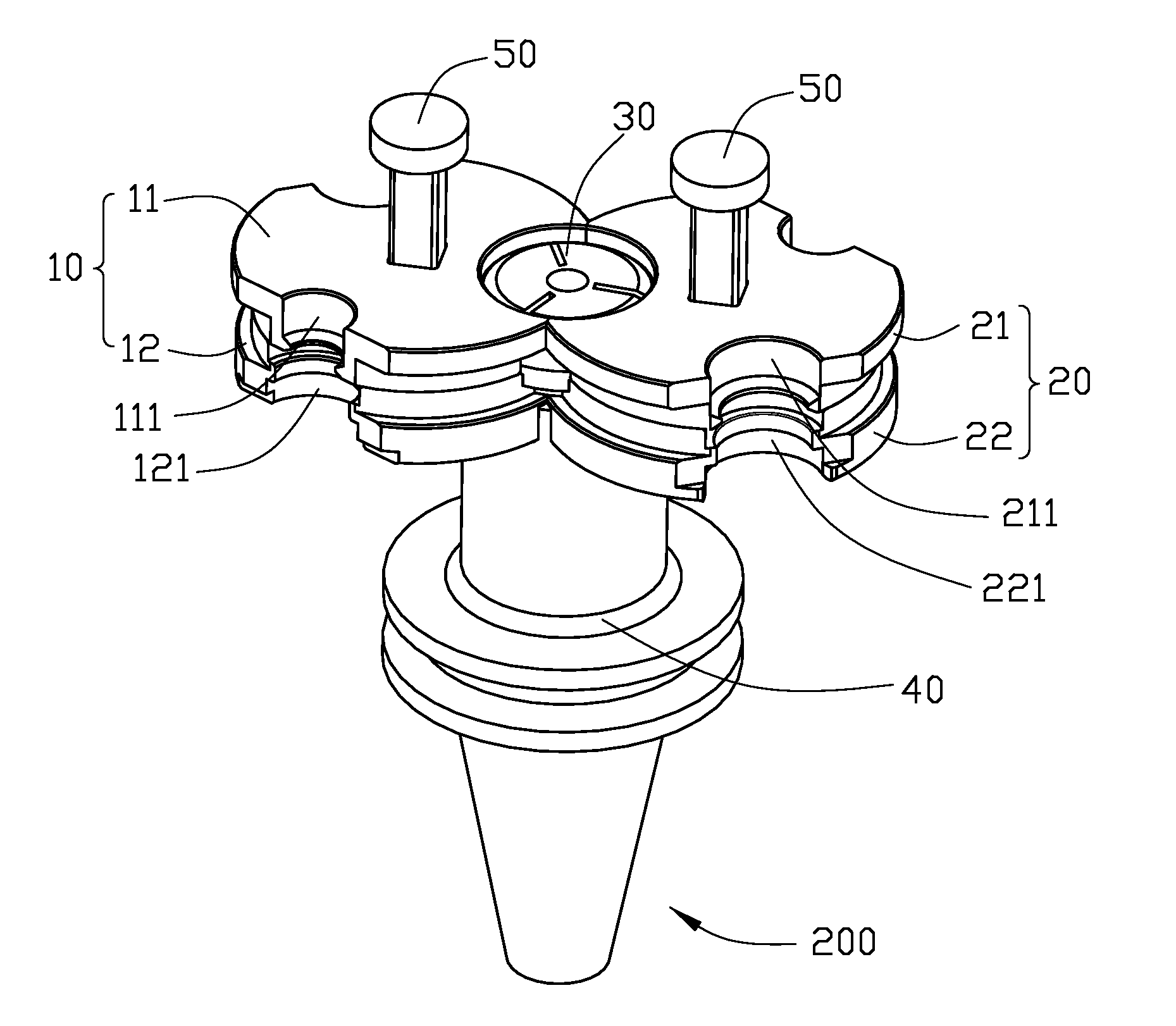
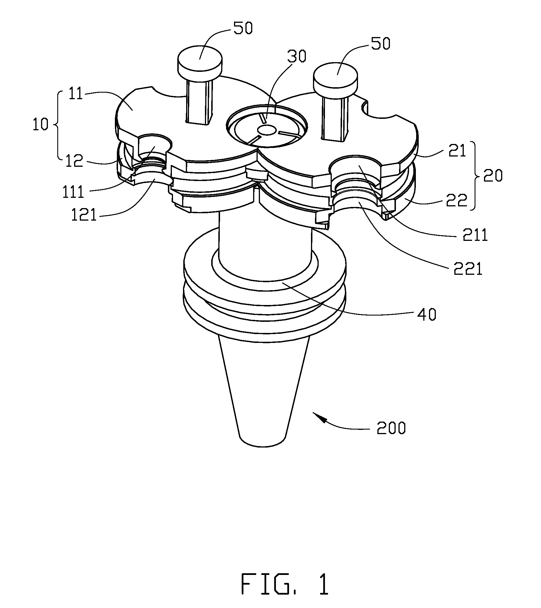
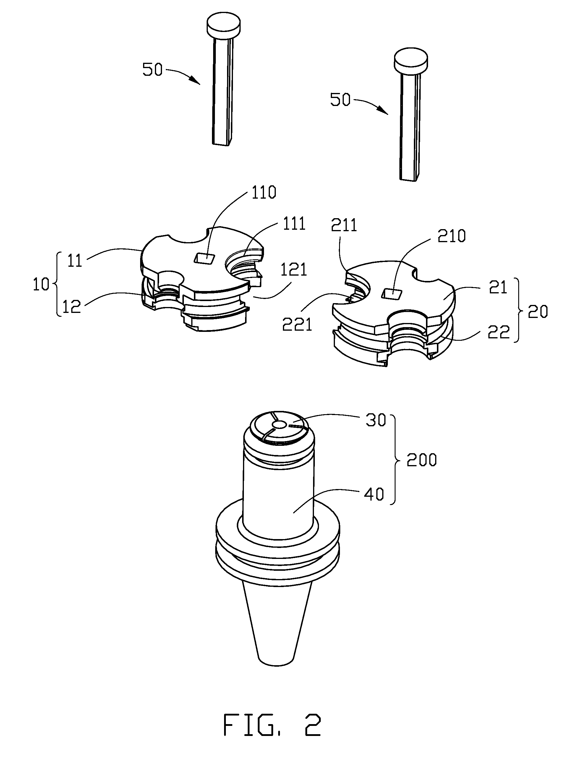
[0024]Referring to FIGS. 1, 5, and 9, a pressing device 100 in accordance with a preferred embodiment is shown. The pressing device 100 includes a first movable member 10, a second movable member 20, a pair of mounting shafts 50, and a driving structure 60. The pressing device 100 is configured for latching and releasing a chucking device 200. The chucking device 200 includes a collet 30 and a collet holder 40. The collet 30 is configured to receive a cutting tool 80 (see FIG. 5), for example a milling cutter. A cylindrical bore (not labeled) defined in the collet 30 serves to accommodate the shank of the cutting tool 80. A plurality of radially directed slots (not labeled) is defined in a side wall of the collet 30 for increasing the radial elasticity of the collet 30. The collet holder 40 is configured to clamp one end of the collet 30. A tapered recess 42 co...


PUM

PropertyMeasurementUnit
Timeaaaaaaaaaa
Sizeaaaaaaaaaa

Abstract

An exemplary pressing device (100) includes a first movable member (10) and a second movable member (20). Each of the first and second movable members includes an upper clamping element (11, 21) and a lower clamping element (12, 22). The upper clamping element has a first fringe portion and a plurality of first latching grooves (111, 211) having different sizes are defined in the first fringe portion. The lower clamping element has a second fringe portion and a plurality of second latching grooves (121, 221) having different sizes are defined in the second fringe portion. Each first latching groove of the second movable member has a same size as that of a corresponding first latching groove of the first movable member. Each second latching groove of the second movable member has a same size as that of a corresponding second latching groove of the first movable member.

Description

BACKGROUND OF THE INVENTION[0001]1. Field of the Invention[0002]The present invention generally relates to pressing devices, and more particularly, to a pressing device for latching and releasing a chucking device which is used for holding a cutting tool.[0003]2. Discussion of the Related Art[0004]A cutting tool, for example a milling cutter, is generally used in a machining process for machining a mold or any other workpieces. Before the machining process, the cutting tool should be mounted in a chucking device. The chucking device together with the cutting tool is then mounted in a machine tool.[0005]A typical chucking device generally includes a collet and a collet holder. The principle of the chucking device is disclosed in U.S. Pat. No. 6,908,085. The chucking device is suitable for tools, in particular cutting tools. A cylindrical bore defined in the collet serves to accommodate the shank of the tool. A plurality of radially directed slots is defined in a sidewall of the colle...

Claims


Application Information

Patent Timeline
IPC IPC(8): B23B31/06
CPCB23B31/201B23B2231/2008B23P11/00B23P19/02Y10T29/53678Y10T483/15Y10T279/3481Y10T29/53961Y10T29/53983B23B31/2073
Inventor YANG, MING-LUZHANG, YA-DONG
Owner HONG FU JIN PRECISION IND (SHENZHEN) CO LTD
Why Eureka
Try Eureka