
Optical fiber shape sensing systems

a technology of optical fibers and shape sensing, applied in the field of optical fibers with bragg gratings, can solve the problems of limited utility of conventional technology for elongating medical instrument applications

Active Publication Date: 2008-11-20
KONINKLIJKE PHILIPS ELECTRONICS NV
View PDF99 Cites 227 Cited by
  • Summary
  • Abstract
  • Description
  • Claims
  • Application Information

AI Technical Summary

Benefits of technology

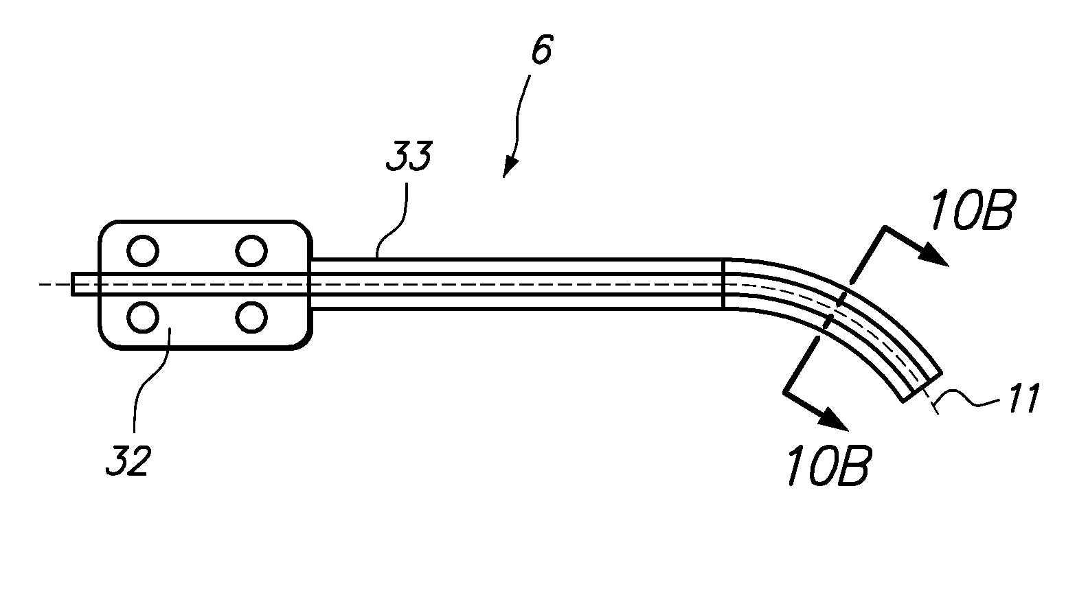
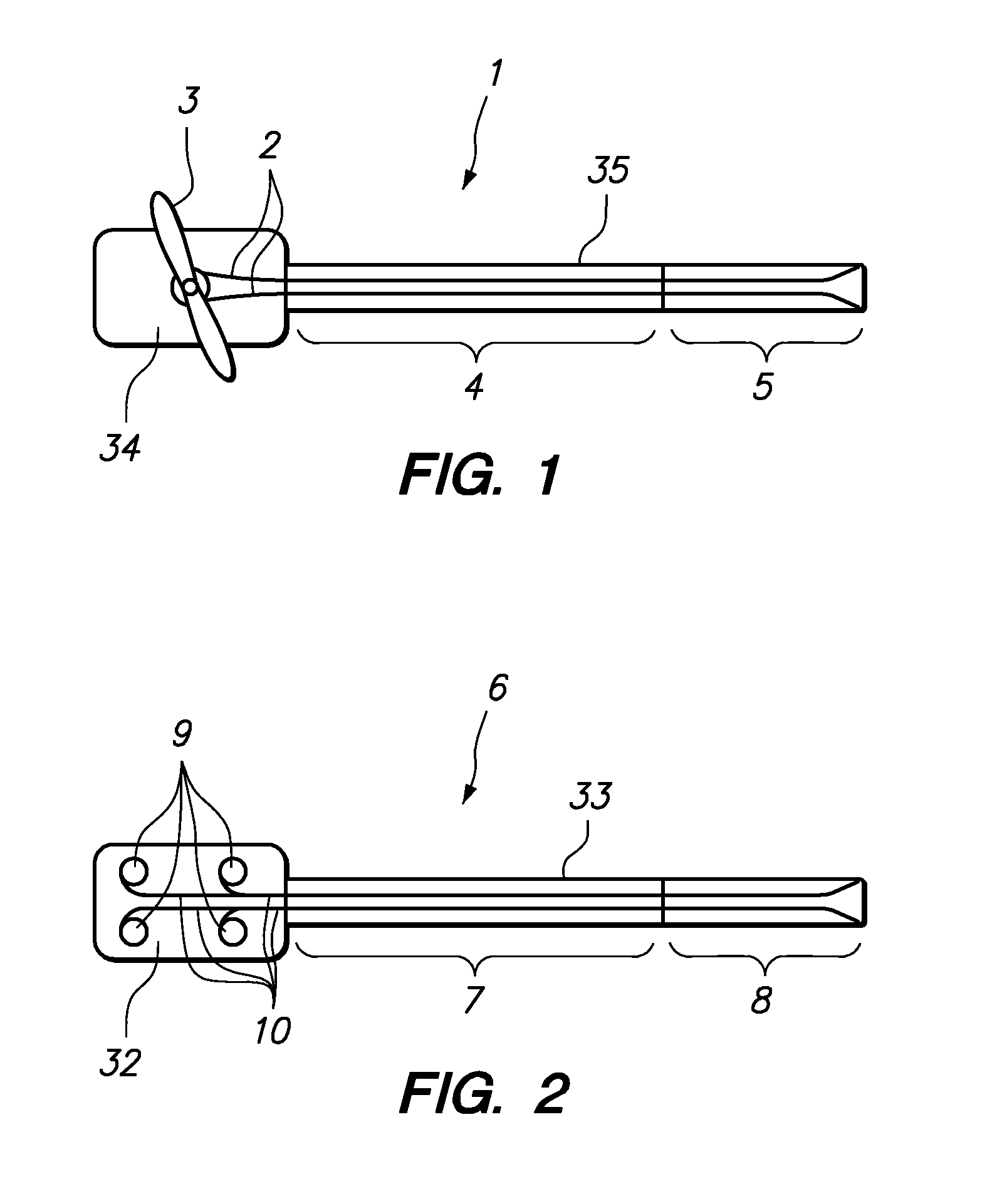
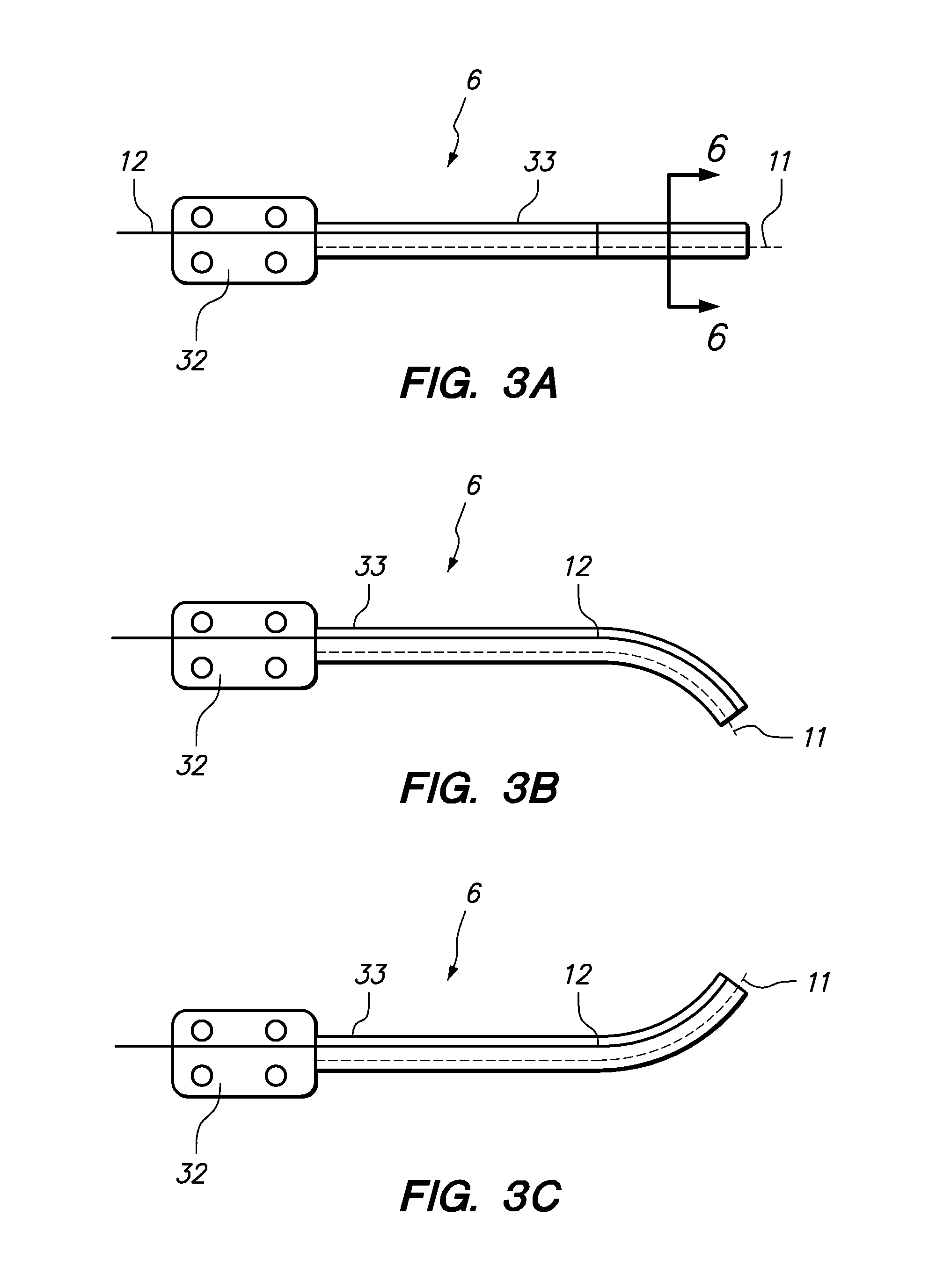
[0015]In accordance with yet another aspect of the invention, a medical instrument system including an elongate body with an optical fiber coupled to the elongate body, the optical fiber including one or more fiber gratings. A localization sensor (e.g., of a type selected from the group comprising electromagnetic sensors, potential difference sensors, and ultrasound sensors) is also coupled to the elongate body. A detector is operatively coupled to the optical fiber and configured to detect respective light signals reflected by the one or more fiber gratings. A controller is operatively coupled to the detector and configured to determine a bending, a twist, or both, of at least a portion of the elongate body based on detected reflected light signals and on a relative position of the localization sensor. In one embodiment, the elongate body is a flexible medical guide instrument. In such embodiment, the optical fiber may optionally be encapsulated in a w...

Problems solved by technology

However, conventional technology has limited utility for elongate medical instrument applications due to hardware geometric constraints, electromagnetivity issues, etc.

Method used


Image

  • Optical fiber shape sensing systems
  • Optical fiber shape sensing systems
  • Optical fiber shape sensing systems

Examples


Embodiment Construction

[0076]Reference will now be made in detail to the preferred embodiments of the present invention, examples of which are illustrated in the accompanying drawings. While the invention will be described in conjunction with the preferred embodiments, it will be understood that they are not intended to limit the invention to these embodiments. On the contrary, the invention is intended to cover alternatives, modifications and equivalents that may be included within the spirit and scope of the invention. Furthermore, in the following detailed description of the present invention, numerous specific details are set forth in to order to provide a thorough understanding of the present invention. However, it will be readily apparent to one skilled in the art that the present invention may be practiced without these specific details. In other instances, well-known methods, procedures, and components have not been described in detail so as not to unnecessarily obscure aspects of the present inve...


PUM


Abstract

A medical instrument system includes an elongate flexible instrument body with an optical fiber substantially encapsulated in a wall of the instrument body, the optical fiber including one or more fiber gratings. A detector is operatively coupled to the optical fiber and configured to detect respective light signals reflected by the one or more fiber gratings. A controller is operatively coupled to the detector, and configured to determine a twist of at least a portion of the instrument body based on detected reflected light signals. The instrument may be a guide catheter and may be robotically or manually controlled.

Description

RELATED APPLICATION DATA[0001]The present application claims the benefit under 35 U.S.C. § 119 to U.S. Provisional Patent Application Ser. Nos. 60 / 925,449, filed on Apr. 20, 2007 and U.S. Provisional Patent Application Ser. No. 60 / 925,472, filed on Apr. 20, 2007, the contents of which are incorporated herein by reference as though set forth in full.[0002]The present application may also be related to subject matter disclosed in the following applications, the contents of which are also incorporated herein by reference as though set forth in full: U.S. patent application Ser. No. 11 / 073,363, filed on Mar. 4, 2005; U.S. patent application Ser. No. 11 / 481,433, filed on Jul. 3, 2006; U.S. patent application Ser. No. 11 / 690,116, filed on Mar. 22, 2007; and U.S. patent application Ser. No. 12 / 012,795, filed on Feb. 1, 2008.FIELD OF INVENTION[0003]The invention relates generally to optical fibers with Bragg gratings that are configured to provide real-time feedback of its own dynamic shape...

Claims


Application Information

Patent Timeline
IPC IPC(8): G02B6/00
CPCA61B5/1076A61B5/6852A61B2017/00039G02B6/022A61B2019/467A61B2019/5261A61B2017/00053A61B2090/067A61B2034/2061A61B1/009
Inventor YOUNGE, ROBERT G.RAMAMURTHY, BHASKAR S.TANNER, NEAL A.SCHLESINGER, RANDALL L.UDD, ERIC
Owner KONINKLIJKE PHILIPS ELECTRONICS NV
Learn More