
Magnetostrictive electrical switching device

Inactive Publication Date: 2008-11-20
ABB (SCHWEIZ) AG
View PDF2 Cites 9 Cited by
  • Summary
  • Abstract
  • Description
  • Claims
  • Application Information

AI Technical Summary

Benefits of technology

[0011]Exemplary embodiments disclosed herein can provide a release which can be used for all types of such switching devices, in which case the basic construction should be the same and modifications can only be carried out so as to match the current level.

Problems solved by technology

The problem with such a release can consist in the fact that opening of the hinged armature is sometimes not possible because an adhesion process is possible on the yoke face, from which the armature is drawn away, as a result of environmental influences and other influences, with the result that a residual current circuit breaker does not trip even in the event of the occurrence of a residual current.
Nonetheless, it is not possible to prevent moisture or the like from entering the housing through the opening, through which the pin is passed to the outside.
In any case, the embodiment of such an electromagnetic release is very complex.
A release for a residual current circuit breaker, however, is suitable neither for a contactor nor for a line circuit breaker; conversely, an electromagnetic release, which can be accommodated in a line circuit breaker, is unsuitable for a residual current circuit breaker at least when the release is intended to respond independently of the system voltage.

Method used


Image

  • Magnetostrictive electrical switching device
  • Magnetostrictive electrical switching device
  • Magnetostrictive electrical switching device

Examples


Embodiment Construction

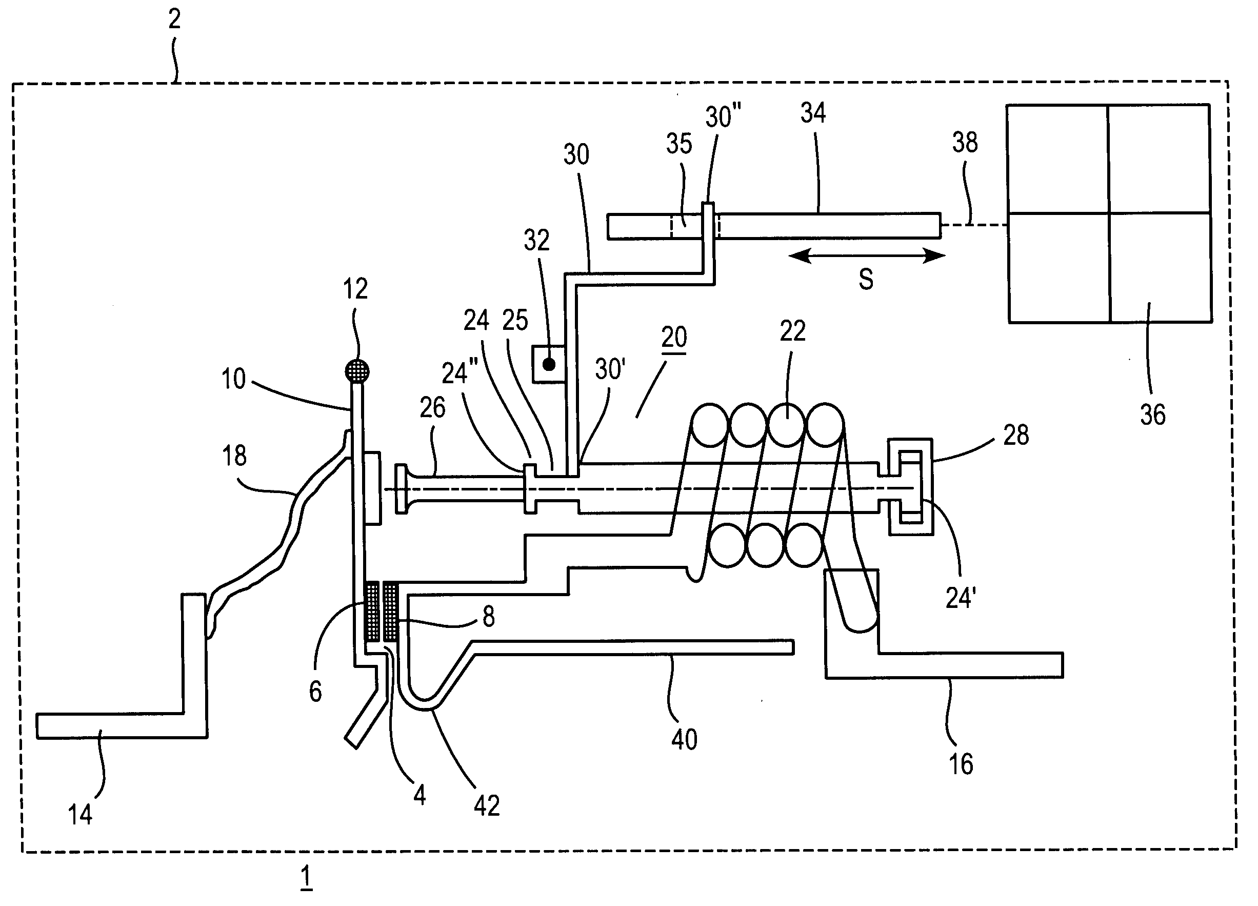
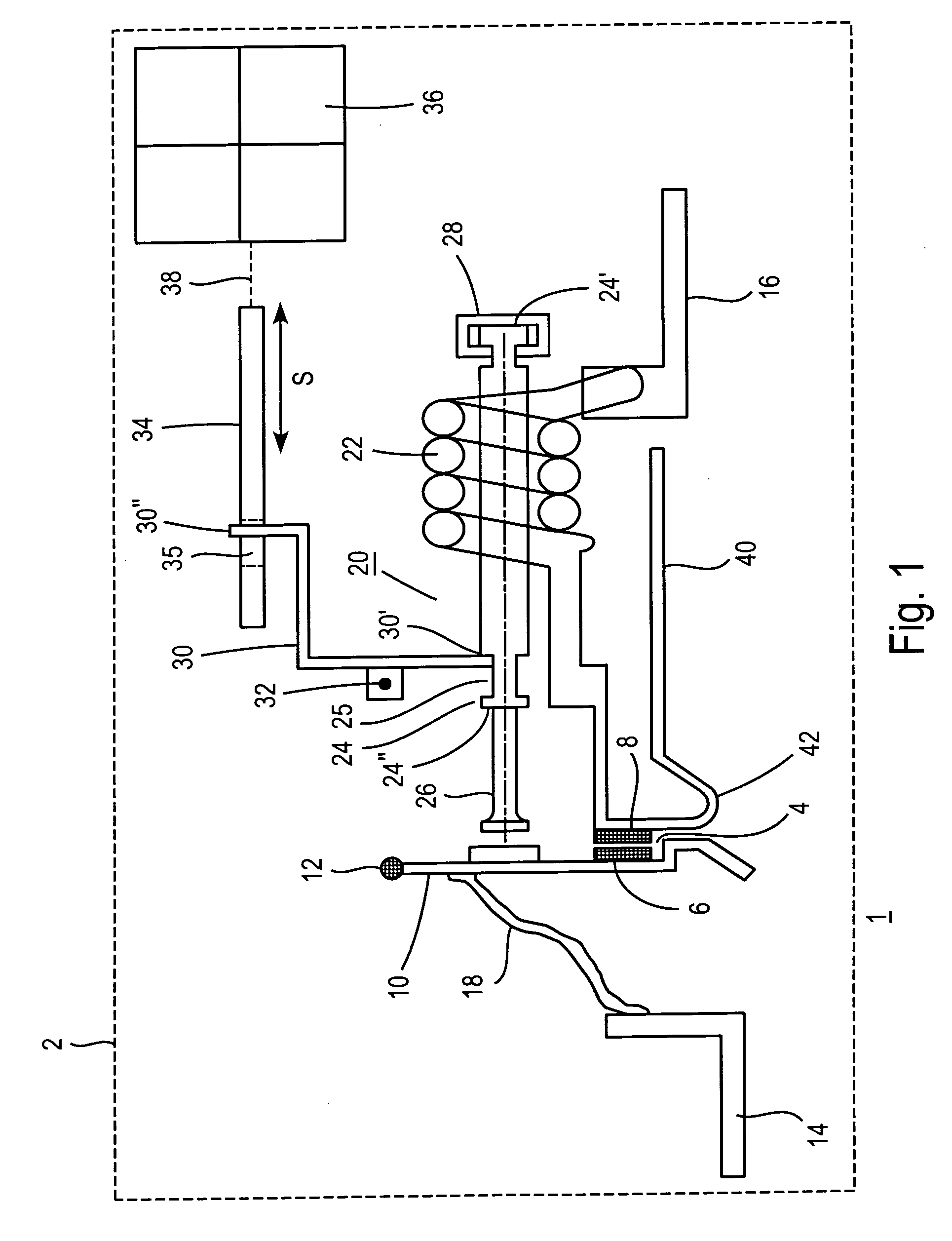
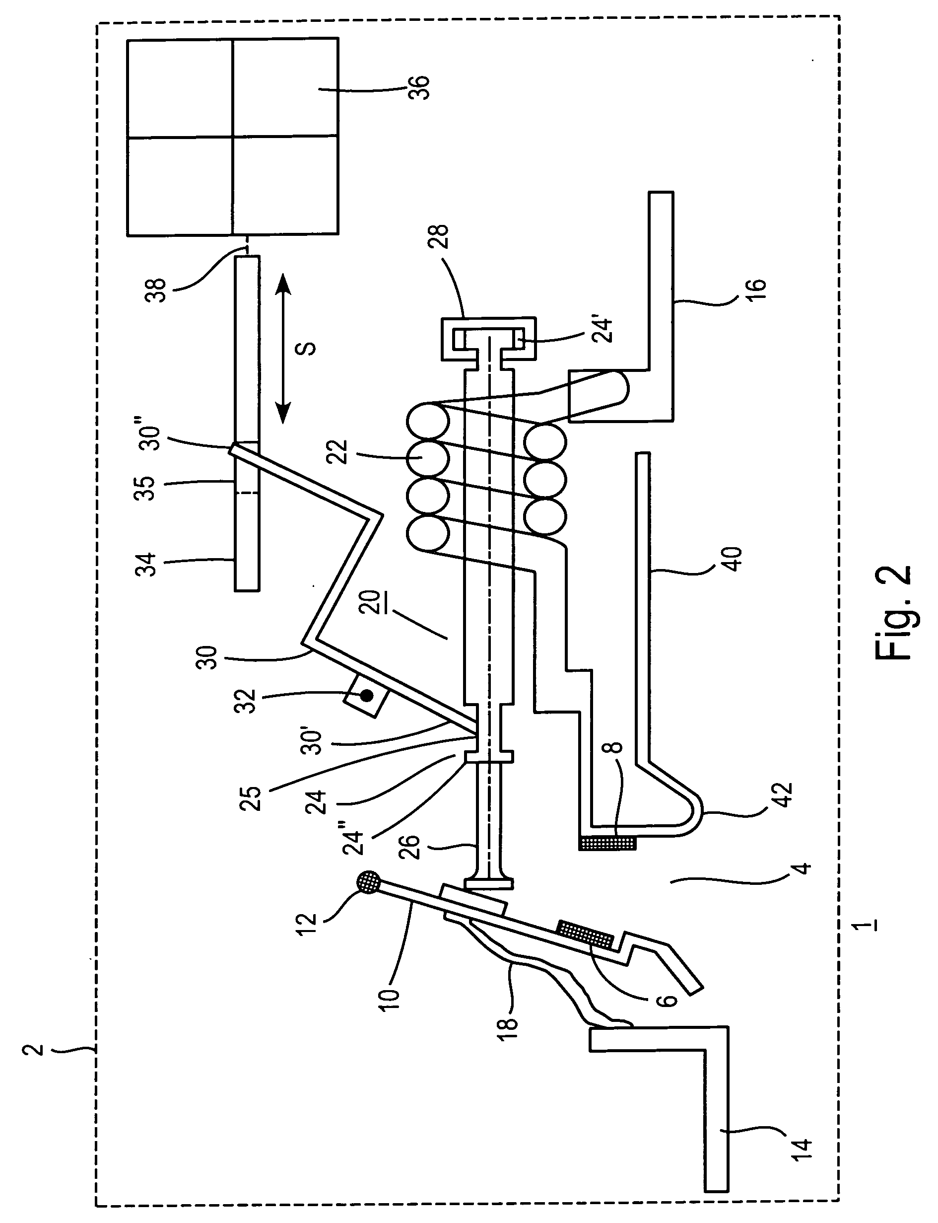
[0023]According to the disclosure, an exemplary actuator comprises an element with a predetermined length, which comprises a shape memory alloy which changes its length under the influence of an electromagnetic field.

[0024]In this case, the element can be positioned in the direct vicinity of a device which produces an electromagnetic field, with the result that this field influences the element.

[0025]In another exemplary configuration, the device can be a coil, which surrounds the element, which is in the form of an elongate spindle.

[0026]WO 98 / 08261 has disclosed such shape memory alloys; see pages 2-5, end of 2nd paragraph, which is incorporated by reference. This document also states at which electrical field intensity the material responds; initially no mention is made of any applications.

[0027]A further document, which describes such shape memory alloys has been published under the number WO 99 / 45631, which is incorporated by reference.

[0028]Reference is made to FIG. 1.

[0029]FI...


PUM


Abstract

The disclosure proposes an electrical switching device having at least one contact point having at least one drive, which opens the contact point directly and / or via a switching mechanism with a latching point and which drive has an element having a predetermined shape, which element consists of a shape memory alloy, which changes its shape under the influence of an electromagnetic field and, in the process, opens or closes a contact point or double contact point or unlatches a switching mechanism.

Description

RELATED APPLICATION[0001]This application claims priority as a continuation application under 35 U.S.C. §120 to PCT / EP2005 / 012219 filed as an International Application on 15 Nov. 2005 designating the U.S., the entire content of which is hereby incorporated by reference in its entirety.TECHNICAL FIELD[0002]The disclosure relates to an electrical switching device with at least one contact point, which is opened by means of an actuator directly or via a switching mechanism with a latching point, the actuator opening the latching point and / or the contact point.BACKGROUND INFORMATION[0003]Electrical switching devices in this sense are line circuit breakers, residual current circuit breakers, motor circuit breakers or the like and contactors.[0004]In the case of line circuit breakers, a switching mechanism is provided which has a latching point, which, on the one hand, is unlatched by a thermal release, for example by a bimetallic strip or a strip of a shape memory alloy, with the result ...

Claims


Application Information

Patent Timeline
IPC IPC(8): H01H55/00
CPCC08L2201/12H01H55/00H01H71/127H01H71/145H01H2300/034
Inventor CLAEYS, PATRICKBECKER, JOACHIMWEBER, RALFKOMMERT, RICHARD
Owner ABB (SCHWEIZ) AG
Learn More