
Apparatus for cleaning inkjet head and cleaning method thereof

a recording apparatus and inkjet head technology, applied in the direction of cleaning process and apparatus, cleaning using liquids, printing, etc., can solve the problems of pigment ink formed by evaporating and drying the water content of pigment ink on the ejection face, serious damage to the ejection face, and the presence of a high molecular compound in the ink, etc., to achieve efficient and surely remove the ink residue

Active Publication Date: 2008-11-20
CANON KK
View PDF12 Cites 10 Cited by
  • Summary
  • Abstract
  • Description
  • Claims
  • Application Information

AI Technical Summary

Benefits of technology

[0018]Therefore, an object of the present invention is to efficiently and surely remove the ink residue from the ejection face, and thereby the original performance that the recording head has is maintained.
[0022]According to the present invention, the ink residue is incorporated in the head liquid by applying, stirring and mixing the head liquid with the ink residue. For example, by performing the wiping operation such that the wiper is relatively largely bent to cause the abdomen thereof to slidingly contact the head surface (ejection face), the application, stirring and mixing of the head liquid are efficiently performed. Then, by performing the wiping operation such that the edge portion of the top end of the wiper slidingly contacts the surface, the mixture of the head liquid and the ink residue can efficiently be scraped. By carrying out the above steps, the ink residue can efficiently be removed from the ejection face, and thereby the surface properties of the ejection face are inhibited from changing to maintain the original properties which the recording head has. As a result, a stable image quality can be maintained.
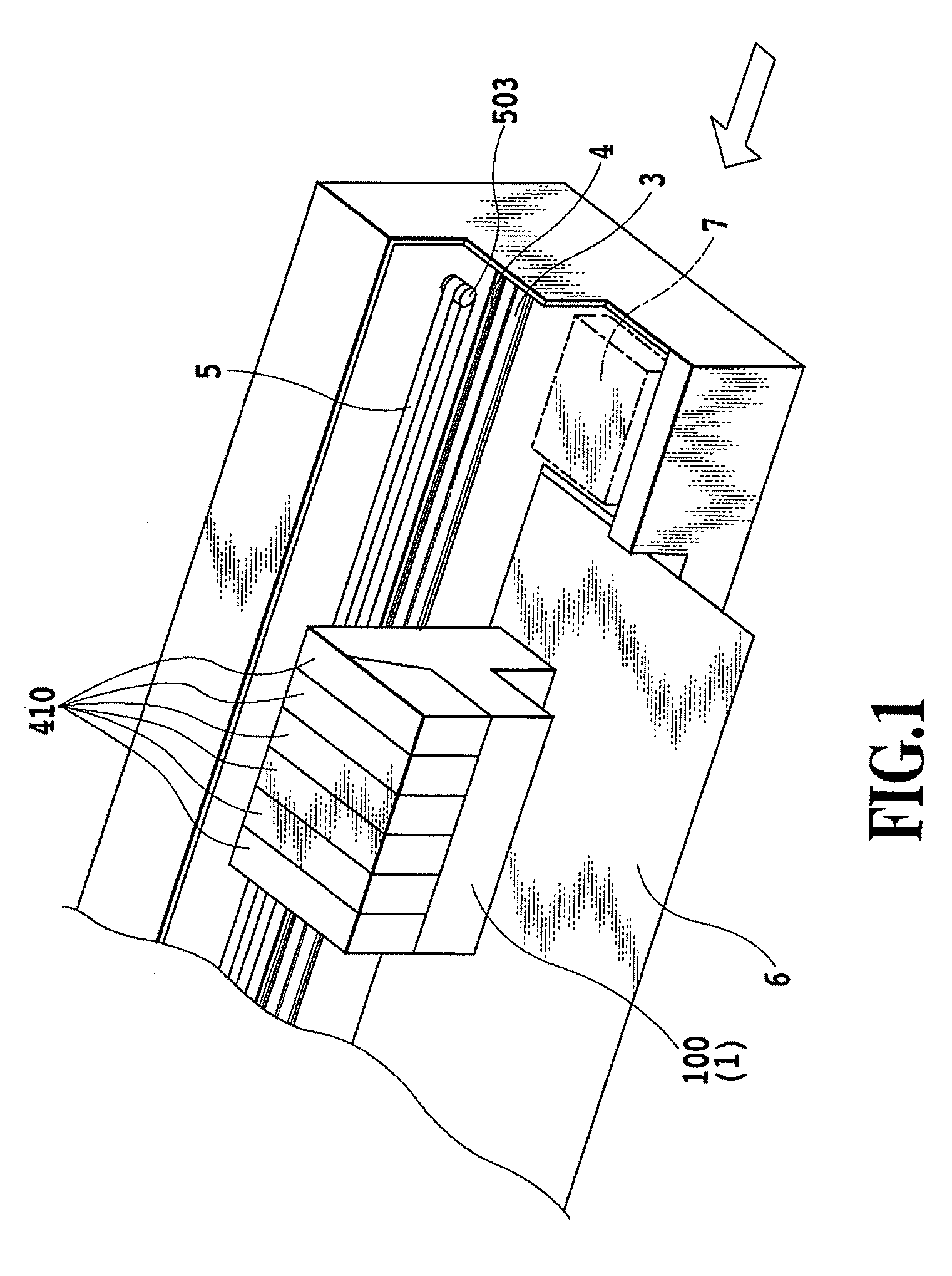
[0064]The carriage 100 stops at the home position as necessary at the time of starting recording or during recording. A cap and a maintenance mechanism 7 including a cleaning device described below in FIG. 6 are provided near the home position. The cap is supported in a manner capable of being ascended and descended. In an ascended position, the cap can cap the ejection face of the head unit 1, and thereby it is possible to protect the face at the non-recording operation time or to perform a suction recovery. At a recording operation time, the cap is set in a descended position to avoid the interference with the head unit 1, or it is possible to receive preliminary ejection by facing to the ejection face.
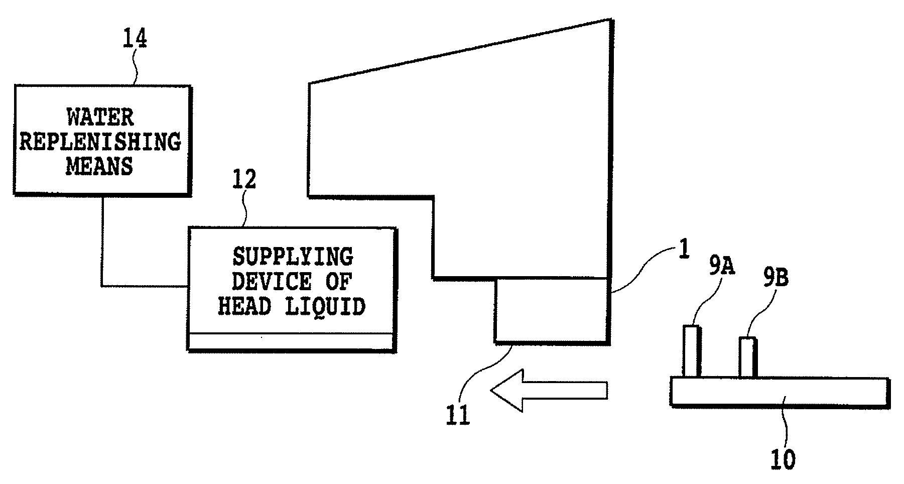
[0069]FIG. 7 is an explanatory drawing of this process. The wiper blade 9A bends to a relatively large extent, and thus the side section (abdominal part) thereof slidingly contacts the ejection face 11 to efficiently transfer and apply the head liquid 16 to the ejection face 11. Even if there is an ink residue 1104 on the ejection face 11, the ink residue 1104 is dissolved by applying the head liquid 16. The top end section (edge) of the wiper blade 9B touches the ejection face 11 in this state so as to efficiently scrape off the dissolved matter of the ink residue. Thus, the cleaning of the recording head is performed.
[0071]However, it is desirable to provide means (a sponge, scraper, or the like) which touches the wiper blades 9A and 9B near the supplying device 12 to actively receive the dissolved matter from the wiper blades, or the above process, and thereby to clean the wiper blades. If the head liquid is transferred after the wiper blades 9A and 9B are made into a cleaned state, it is possible to prepare for the next wiping operation immediately.

Problems solved by technology

Furthermore, dust drifting in the air may sometimes adhere thereto.
Accordingly, the dried matter of the pigment ink formed by evaporating and drying the water content in the ink on the ejection face damages the ejection face seriously as compared to the dried sticky matter of a dye-based ink in which a color material itself is dissolved at a molecular level.
This is a problem which occurs even in inks other than the pigment-based one in a case where a reaction liquid is added to an ink for the purpose of controlling the viscosity of the ink, improving light-resistance and for others, resulting in the presence of a high molecular compound in the ink.
In this case, the mixing of the head liquid and the ink residue cannot be favorably performed, and the wiping off the ejection face becomes incomplete.
As a result, the desired cleaning may not be able to be achieved.
Moreover, when the wiping operations are performed in a state where the head liquid is not adequately applied, the ejection face may be deteriorated.
Furthermore, in the configuration disclosed in Patent Document 4, the head liquid is adhered to the surface only, and the head liquid and the ink residue may not sufficiently be mixed.
As a result, the desired cleaning may not be achieved.

Method used


Image

  • Apparatus for cleaning inkjet head and cleaning method thereof
  • Apparatus for cleaning inkjet head and cleaning method thereof
  • Apparatus for cleaning inkjet head and cleaning method thereof

Examples


example

Surface Tension

[0094]Firstly, here, explained is the surface tension described in the present specification.

[0095]In the measurement of the surface tension of the ejection face (surface tension of a solid), the wetting test standard solution (wetting reagent) described in JIS K6768-1971 on the ejection face using a cotton swab was firstly applied. Subsequently a wetting reagent-repelling degree in the state immediately after the application (the state of “tailing” of the wetting reagent with the movement of the cotton swab at the time of application) was observed. The measurement method judged the wetting reagent to be “repelling” when the wetting reagent formed a round droplet immediately after the application, and to be “wetting” when the droplet immediately after the application was not a perfect circle. The measurement was carried out in order of the wetting reagent with low surface tension. The surface tension of the wetting reagent applied immediately before a wetting reagent ...


PUM


Abstract

In a method of cleaning an ejection face by supplying a head liquid on a surface (ejection face) of an inkjet head provided with ink ejection outlets, and then by performing wiping operations thereon, an ink residue on the ejection face is efficiently and surely removed from the ejection face to achieve a sufficient cleaning thereon. For this purpose, a first wiping operation is first performed such that a wiper (9A) is relatively largely bent, and slidingly contacts the ejection face at an abdomen thereof to efficiently perform the application, stirring and mixing of the head liquid. Then, a second wiping operation is performed such that an edge portion of the top end of a wiper (9B) slidingly contacts the surface to efficiently scrape the mixture of the head liquid and the ink residue.

Description

BACKGROUND OF THE INVENTION[0001]1. Field of the Invention[0002]The present invention relates to an inkjet recording apparatus and a method of cleaning an inkjet head which is used in the apparatus. The present invention specifically relates to a technology for cleaning the inkjet head (hereinafter also referred to as a recording head or simply a head) by efficiently removing an ink residue and the like adhered on the surface (hereinafter also referred to as an ejection face) of the inkjet head, on which ink ejection outlets are formed.[0003]2. Description of the Related Art[0004]A clean-up (cleaning) technique for a recording head which ejects an ink is a very important factor of an inkjet recording method because the method is the system in which input image data is converted to the output image using a liquid ink as a medium. Main problems in requiring the cleaning are briefly described as follows.[0005]An ink ejection recording head directly ejects an ink through a fine nozzle (...

Claims


Application Information

Patent Timeline
Patent Type & Authority Applications(United States)
IPC IPC(8): B08B1/00B08B13/00B41J2/165
CPCB41J2/16538B41J2/16552
Inventor NAGAI, SOUICHISANADA, MIKIOMATSUMOTO, NOBUYUKIKOITABASHI, NORIBUMI
Owner CANON KK
Learn More