
Automated sampling system

a sampling system and automatic technology, applied in the field of sample carriers, can solve the problems of unreliable holding and centering of conventional sample carriers, and achieve the effect of limiting the vertical movement of sample carriers and minimizing the chance of carry-over contamination

Inactive Publication Date: 2008-11-20
GEN PROBE INC
View PDF99 Cites 13 Cited by
  • Summary
  • Abstract
  • Description
  • Claims
  • Application Information

AI Technical Summary

Benefits of technology

The solution ensures minimal force is required for cap penetration and effectively prevents cross-contamination by centering caps and immobilizing sample tubes, enhancing the reliability of automated sampling systems.

Problems solved by technology

While these sample carriers are generally adequate to hold open-ended sample tubes during transport and pipetting in an automated sampling system, they do not include a mechanism for maintaining the sample tubes in fixed vertical orientations or for centering sample tubes having vessel components of varying diameters.
As a result, conventional sample carriers are unreliable for holding and centering sample tubes having penetrable caps whose design and construction requires accurate positioning of the sample tubes in order to minimize the forces needed to penetrate the caps with a robotic pipettor.

Method used


Image

  • Automated sampling system
  • Automated sampling system
  • Automated sampling system

Examples


Embodiment Construction

[0039]While the present invention may be embodied in a variety of forms, the following description and accompanying drawings are merely intended to disclose some of those forms as specific examples of the present invention. Accordingly, the present invention is not intended to be limited to the forms or embodiments so described and illustrated. Instead, the full scope of the present invention is set forth in the appended claims.

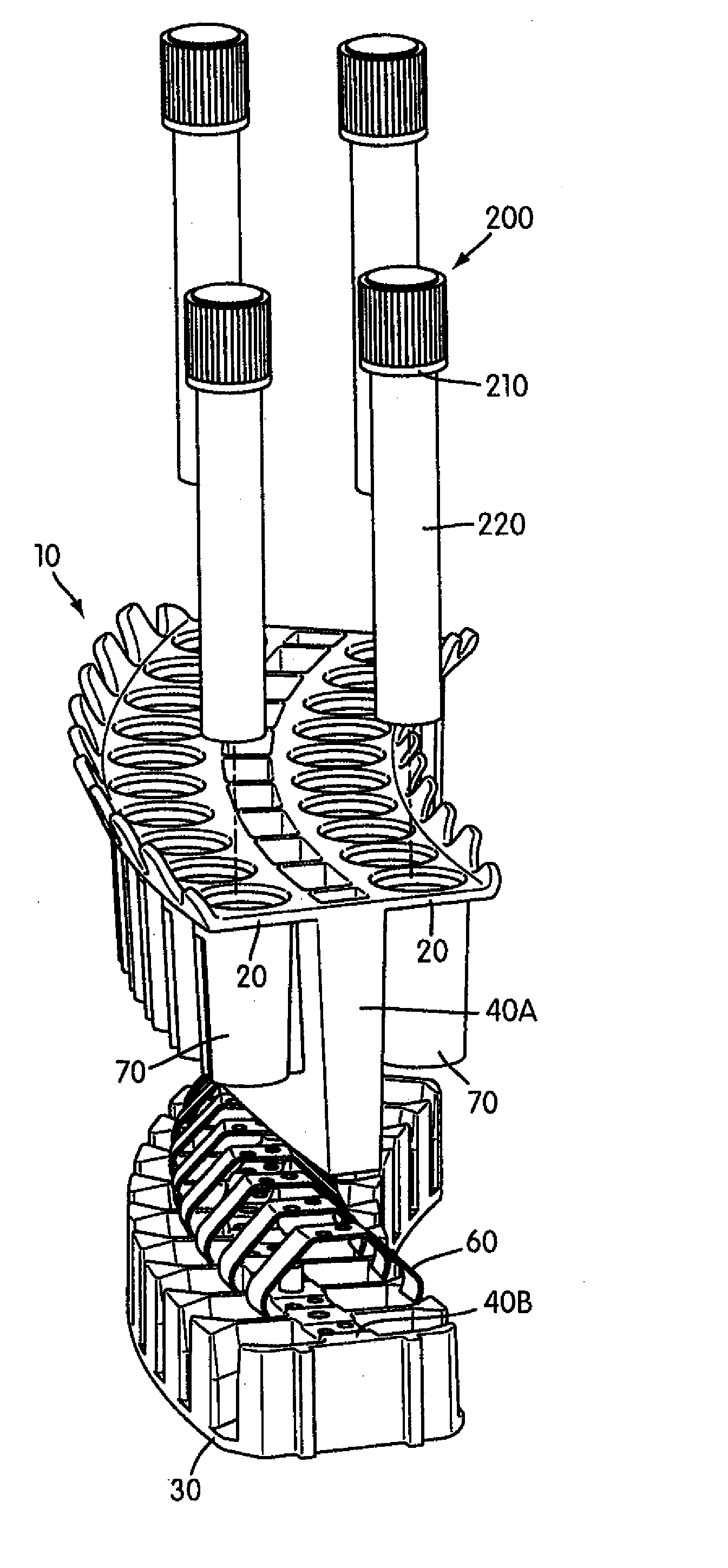
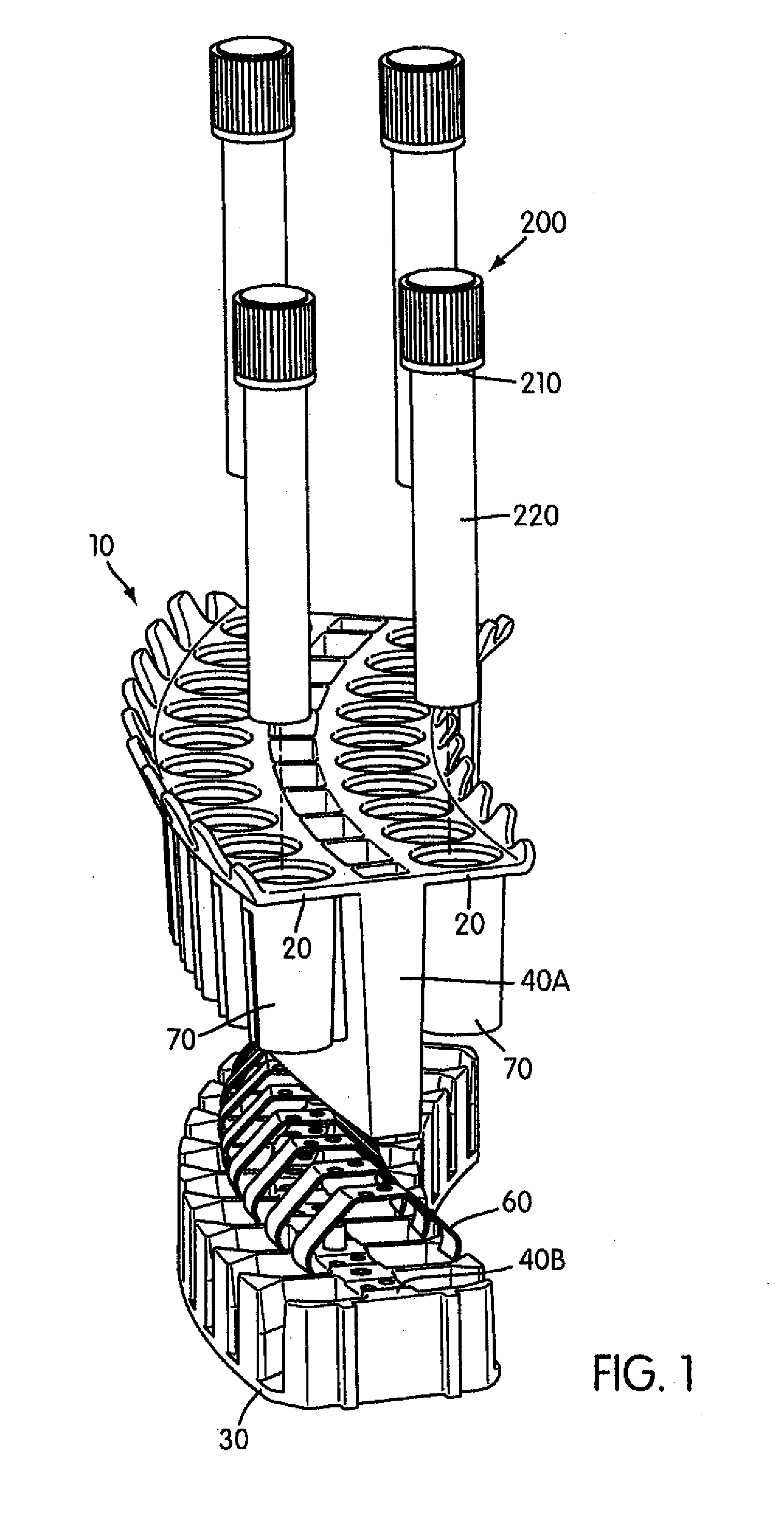
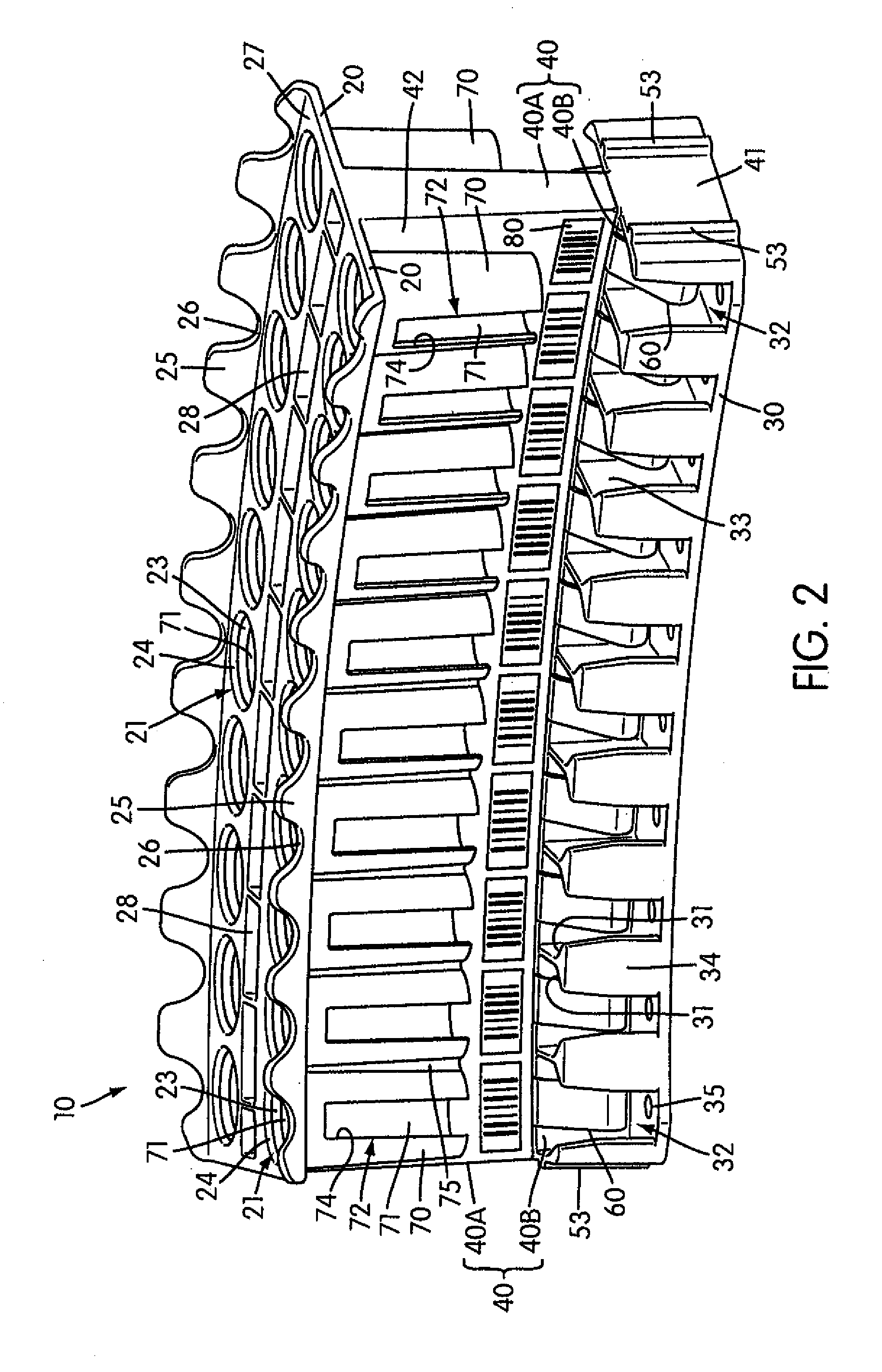
[0040]With reference to the figures, a preferred sample carrier 10 of the present invention is shown alone or in combination with a drip shield 100 for protecting against cross-contamination between sample tubes 200 carried by the sample carrier and for limiting vertical movement of the sample carrier when sample is being removed from any of the sample tubes. Sample carriers 10 of the present invention are preferably used in combination with sample tubes 200 having sealed caps 210 which can be penetrated by standard pipette tips for use with positive displace...


PUM

PropertyMeasurementUnit
angleaaaaaaaaaa
holding forceaaaaaaaaaa
distanceaaaaaaaaaa

Abstract

A sample carrier having a top wall, a base, and a support wall joining the top wall and the base. The top wall includes aligned, spaced-apart openings on at least one side of the support wall which are sized to receive sample tubes. Sleeves depending from the top wall and circumscribing each opening direct sample tubes into sample tube holding areas. The sample tube holding areas each include one or more retaining walls extending upward from the base opposite the support wall. Springs extending outward from the support wall bias sample tubes against the retaining walls. A drip shield comprising a cover plate, a pair of through-holes for accessing sample tubes in the sample carrier, and a depending fin which separates sample tubes on opposite sides of the support wall protects against cross-contamination between sample tubes held by the sample carrier.

Description

CROSS-REFERENCE TO RELATED APPLICATIONS[0001]This application is a divisional of U.S. application Ser. No. 10 / 199,690, filed Jul. 18, 2002, now pending, which claims the benefit of U.S. Provisional Application No. 60 / 307,047, filed Jul. 20, 2001, the contents of each of which applications is hereby incorporated by reference herein.FIELD OF THE INVENTION[0002]The present invention relates to a sample carrier for holding and centering a plurality of sample tubes. The sample carrier of the present invention can be adapted for use with an automated sampling system and is designed for holding sample tubes having penetrable caps. The present invention further relates to a drip shield for protecting against cross-contamination between sample tubes and for substantially limiting vertical movement of sample carriers positioned on conveying means during an automated sample transfer.INCORPORATION BY REFERENCE[0003]All references referred to herein are hereby incorporated by reference in their ...

Claims


Application Information

Patent Timeline
Patent Type & Authority Applications(United States)
IPC IPC(8): B01L3/00B01L9/06G01N35/02G01N35/04G01N35/10
CPCB01L9/06B01L2200/025B01L2200/141G01N35/025G01N35/1079G01N2035/0451G01N2035/0455G01N35/026G01N35/028
Inventor DALE, JAMES D.SEVIGNY, GERARD J.WEBB, MATTHEW W.TSEO, GUS G.
Owner GEN PROBE INC
Learn More