Cooling fan and dynamic pressure bearing structure

Inactive Publication Date: 2008-11-13
DELPHI TAIWAN
View PDF5 Cites 9 Cited by
  • Summary
  • Abstract
  • Description
  • Claims
  • Application Information

AI Technical Summary

Benefits of technology

[0009]An object of the present invention is to provide a cooling fan and dynamic pressure bearing structure with less number of pressure collecting grooves of the dynamic pressure bearing to reduce the processing load and production costs.
[0013]The efficacy of the present invention is as follows: the transverse groove extended from the connecting point of the two slanted grooves in the dynamic pressure bearing are provided to increase the area for creating pressure. Moreover the intensity of the pressure is improved and the number of pressure collecting grooves are decreased to reduce the processing load and production costs.

Problems solved by technology

As such, there are more pressure collecting grooves are requested for the prior dynamic pressure bearings to achieve the predetermined intensity of pressure, so that it makes the producing more complicated and increases the cost.

Method used


Image

  • Cooling fan and dynamic pressure bearing structure
  • Cooling fan and dynamic pressure bearing structure
  • Cooling fan and dynamic pressure bearing structure

Examples


Embodiment Construction

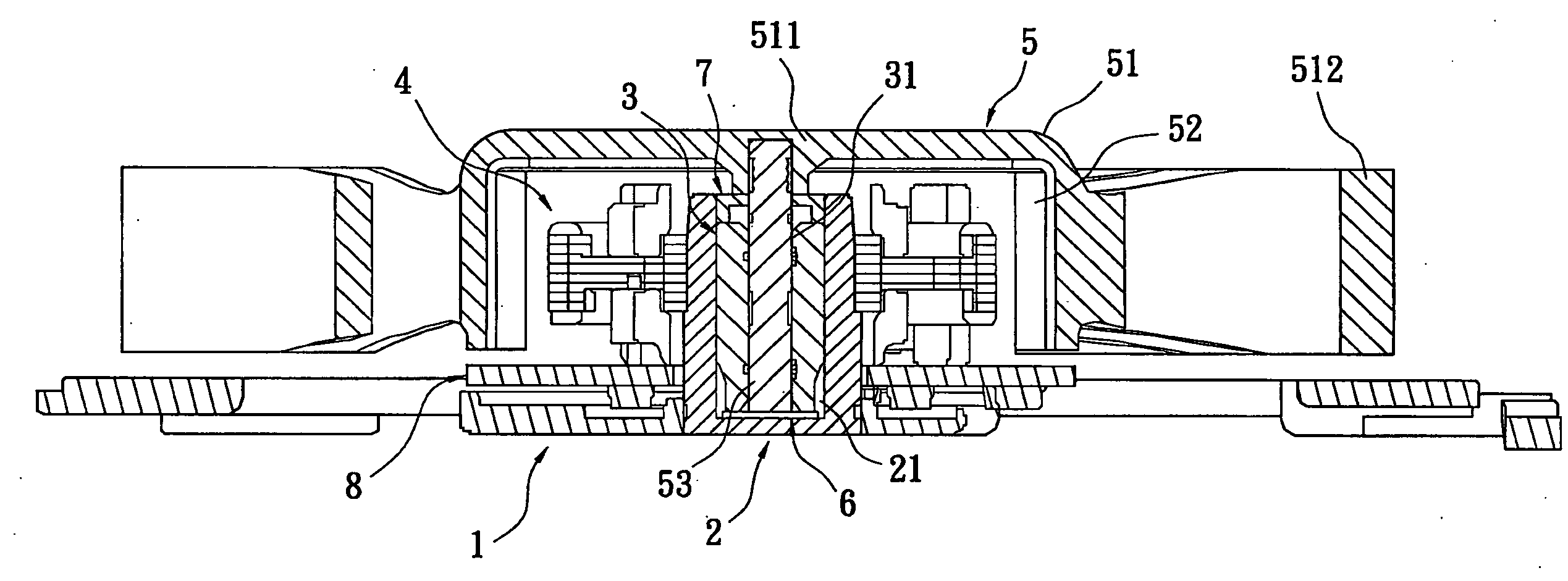
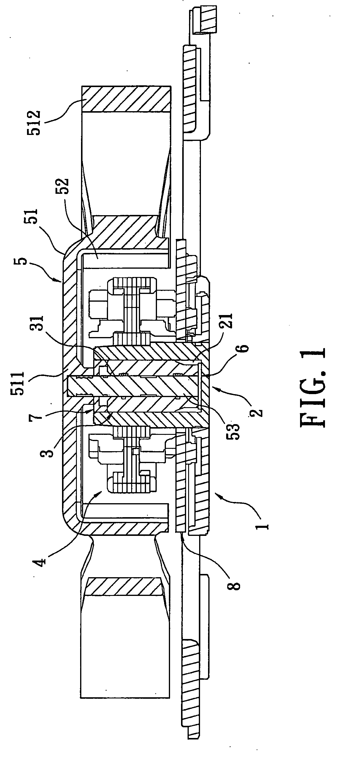
[0020]Please refer to FIGS. 1-4, a cooling fan in accordance with a preferred embodiment of the present invention is shown. The cooling fan includes a base portion 1, a bearing portion 2, a dynamic pressure bearing 3, a coil assembly 4, an impeller assembly 5, a gasket 6 and a cover for preventing oil leakages 7. The base portion is shaped approximately as a board for supporting the bearing portion 2, the dynamic pressure bearing 3, the coil assembly 4, the impeller assembly 5, and other elements.

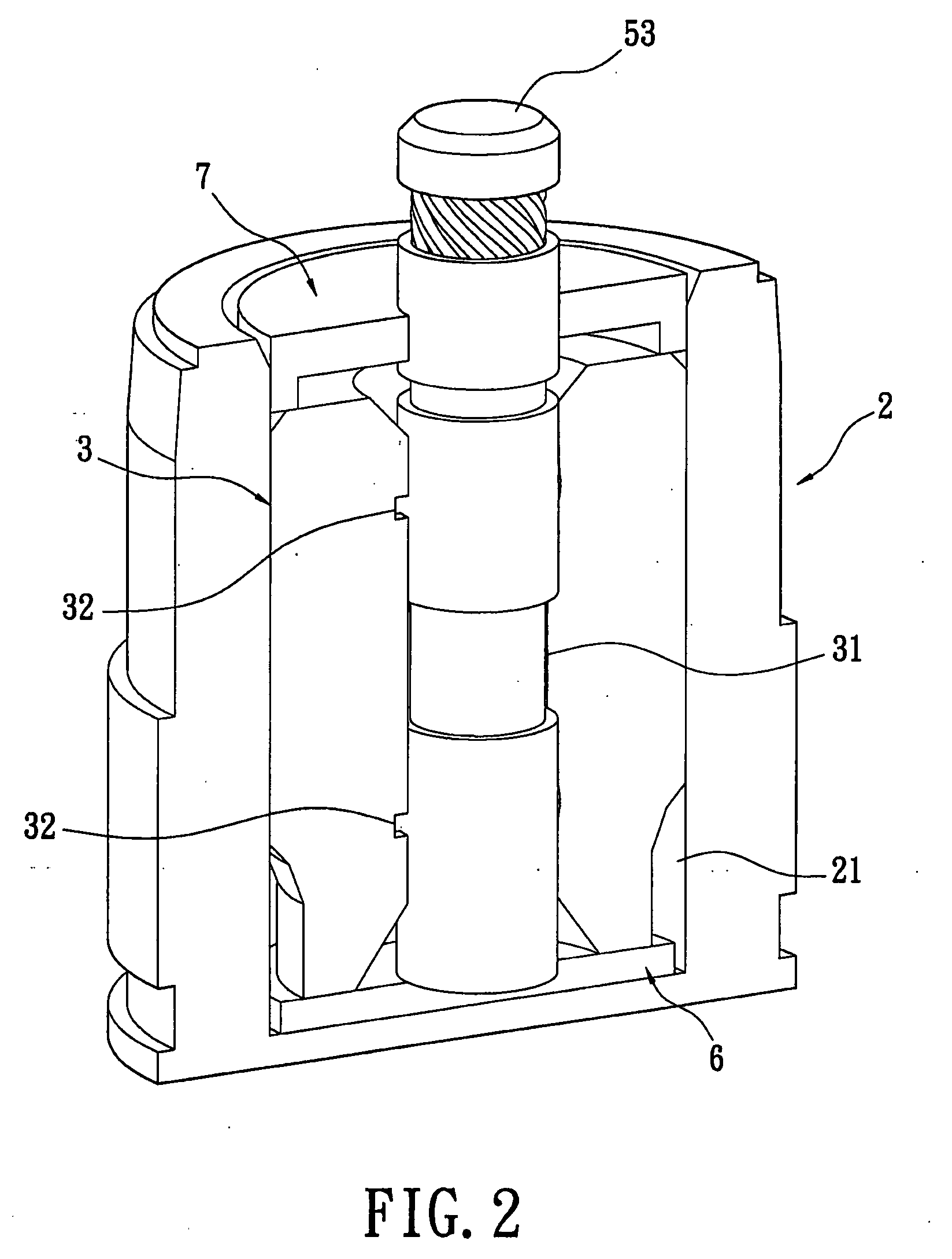
[0021]The bearing portion 2 is formed as a hollow column and there is a internal storage space 21 inside and a top of which is shaped as an opening. The bottom of the bearing portion 2 fixed on the base portion 1 via an injection connection or a riveted joint.

[0022]The dynamic pressure bearing 3 is received in the internal storage space 21 of the bearing portion 2. An external surface of the dynamic pressure bearing 3 is tightly fixed in the internal storage space 21. There is a shaft hole ...


PUM

PropertyMeasurementUnit
Lengthaaaaaaaaaa
Pressureaaaaaaaaaa
Diameteraaaaaaaaaa

Abstract

A cooling fan and dynamic pressure bearing structure is disclosed. The cooling fan includes a base portion, a bearing portion, a dynamic pressure bearing, a coil assembly, and an impeller assembly. The dynamic pressure bearing is received in the bearing portion. A plurality of pressure collecting grooves is arranged in an inner surface of a shaft hole of the dynamic pressure bearing at intervals for receiving lubricating oil. Each pressure collecting groove has two slanted grooves extending slantways which connect with each other at one end to form a connecting point. A transverse groove extends from the connecting point backward the direction of the two slanted grooves. Based on the special design of the pressure collecting groove, the present invention increases the area that creates pressure to increase the intensity of the pressure and decrease the number of pressure collecting grooves to reduce processing loads and production costs.

Description

BACKGROUND OF THE INVENTION[0001]1. Field of the Invention[0002]The present invention relates to a cooling fan and dynamic pressure bearing structure, and particularly to a hydrodynamic pressure bearing may increase the intensity of pressure by increasing the area that creates pressure and reduces the processing load and costs of production by decreasing the number of pressure collecting grooves.[0003]2. Description of the Prior Art[0004]Lubricating oil in hydrodynamic may lubricate the shaft and bearing in order to avoid collisions and damage of the bearing. Prior hydrodynamic bearings classify as static pressure bearing and dynamic pressure bearing.[0005]Lubricating oil is stored inside static pressure bearing at room temperature. When the static pressure bearing is rotating, the shaft can be supported due to the liquid pressure caused by the lubricating oil. If the shaft is deviated, the lubricating oil presses on the deviating side to move the shaft back to the correct position....

Claims


Application Information

Patent Timeline
IPC IPC(8): B23P17/00
CPCF04D29/057F16C17/10F16C33/103F16C33/107F04D25/062F04D25/0626F16C17/107
Inventor CHEN, WEN-PINSU, SHENG-PINLEE, ZHEN-YUTSAI, MENG-JIALAI, MEI-LIN
Owner DELPHI TAIWAN
Why Eureka
Try Eureka