
System and method for interconnecting a plurality of printed circuits

a technology of printed circuits and interconnections, applied in the directions of printed circuit repair/correction, non-printed jumper connection addition, fixed connection, etc., can solve the problem that fuses may be more expensive to install and produce than other alternatives

Active Publication Date: 2008-11-13
APTIV TECH LTD
View PDF33 Cites 27 Cited by
  • Summary
  • Abstract
  • Description
  • Claims
  • Application Information

AI Technical Summary

Benefits of technology

[0006]A fifth aspect of the invention includes a method for providing a fuse assembly for use with a printed circuit board. The method comprises: providing a primary fuse having a first terminal and a second terminal wherein each terminal has shoulders that define mounting tip sections, coupling the first terminal and the second terminal with a primary fusible element capable of regulating electrical current, and permanently connecting the primary fuse to the printed circuit board at the first terminal and the second terminal so that electrical current flows through the primary electrical fuse.

Problems solved by technology

While plug-in blade type fuses have worked successfully, these fuses sometimes may be more expensive to install and produce than other alternatives.

Method used


Image

  • System and method for interconnecting a plurality of printed circuits
  • System and method for interconnecting a plurality of printed circuits
  • System and method for interconnecting a plurality of printed circuits

Examples


Embodiment Construction

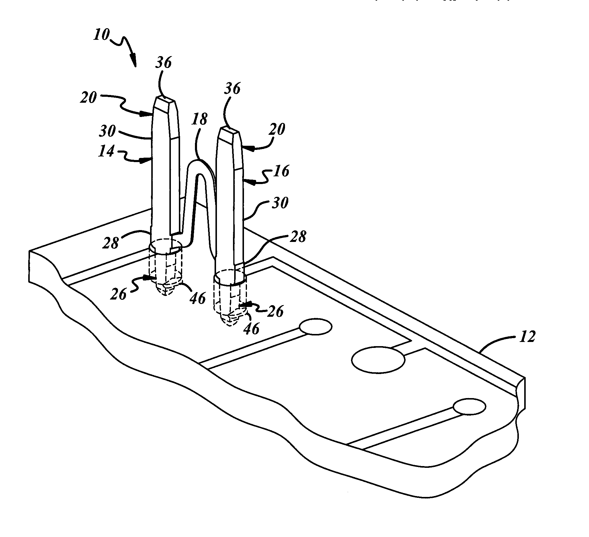
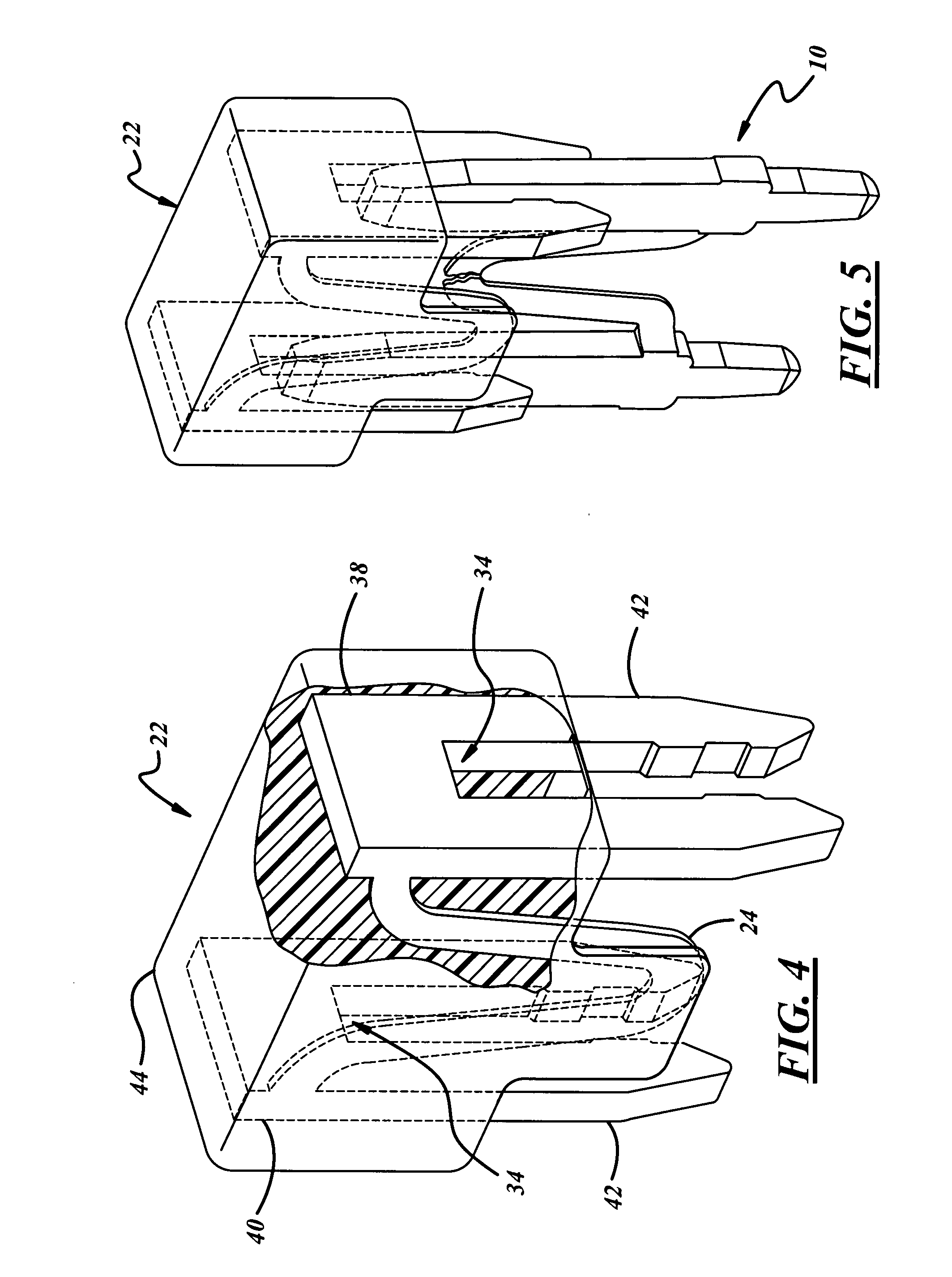
[0012]Referring now to the drawings, FIG. 1 illustrates a primary fuse generally shown at 10 adapted to attach to a printed circuit board. The primary electrical fuse 10 comprises a first terminal generally indicated at 14 and a second terminal generally indicated at 16. A fusible element 18 electrically links the first terminal 14 and second terminal 16. On the first terminal 14 and the second terminal 16 are receiving tip sections generally indicated at 20 capable of receiving a replacement electrical fuse adapted to electrically connect the first terminal 14 to the second terminal 16 with a replacement fusible element. Additionally, at least one of the first terminal 14 and second terminal 16 has a mounting tip section, generally indicated at 26 and defined by shoulders 28, adapting to mount to a printed circuit board.

[0013]A printed circuit board 12, as shown in FIGS. 2 and 3, uses vias to mechanically support and electrically connect a primary fuse 10 to electrically conductive...


PUM


Abstract

A primary electrical fuse is attached to a printed circuit board. The primary electrical fuse comprises a first and second terminal, a fusible element disposed between the first and second terminals electrically linking the first terminal and the second terminal, and receiving tip sections located on the first and second terminals that receive a replacement electrical fuse to electrically connect the first and second terminals with a replacement fusible element.

Description

BACKGROUND OF THE INVENTION [0001]Fuses, or fusible links, are well known and protect electrical circuits from excess current that may harm electrical circuits or devices. Vehicles have used fuses to protect electrical circuits and devices for many years. These fuses often take the form of a plug-in, blade-type fuse. This fuse type usually comprises an all-metal fuse element stamped from a strip of fuse metal. A single-piece housing, having an opening at one end, is then attached to the stamped metal fuse. The opening allows two terminal blades to extend from the housing and plug into a bussed electrical center housing printed circuit boards and regulating current. After the electrical circuit or device connected to the fuse suffers an unwanted increase in current, the plug-in blade type fuse is removed and replaced with a new plug-in blade type fuse. While plug-in blade type fuses have worked successfully, these fuses sometimes may be more expensive to install and produce than othe...

Claims


Application Information

Patent Timeline
IPC IPC(8): H01H85/04H01R12/58H01R12/55
CPCH01H85/0417H01H2085/0412H01H2085/206H01H2085/266H05K3/222H05K3/225H05K3/308H05K2201/09954H05K2201/10181H05K2201/1059H01R12/55H01R12/58
Inventor BANZO, JUAN I.
Owner APTIV TECH LTD
Learn More