
Anode for secondary battery having negative active material with nano-fiber network structure and secondary battery using the same, and fabrication method of negative active material for secondary battery

Inactive Publication Date: 2008-11-06
KOREA INST OF SCI & TECH
View PDF4 Cites 83 Cited by
  • Summary
  • Abstract
  • Description
  • Claims
  • Application Information

AI Technical Summary

Benefits of technology

[0016]Another object of the present invention is to provide a negative active material which can maximize cycling characteristics by minimizing volume expansion and contraction of the negative active material occurring during charging/discharging and which can perform high speed charging/discharging

Problems solved by technology

However, the carbon material (graphite) currently being commercialized and used intercalates one lithium atom per 6 carbon atoms (LiC6) in theory, limiting the theoretical maximum capacity to 372 mAh/g and thus limiting an increase in its capacity.
However, dendrite formation due to the strong reducing power of lithium causes problems related to stability.
However, a very great volume change of 200-350% occurs due to a reaction with lithium when charging/discharging, thereby causing the separation of the negative active material from the collector during repetitive charging/discharging cycles or deteriorating the cycling characteristi

Method used


Image

  • Anode for secondary battery having negative active material with nano-fiber network structure and secondary battery using the same, and fabrication method of negative active material for secondary battery
  • Anode for secondary battery having negative active material with nano-fiber network structure and secondary battery using the same, and fabrication method of negative active material for secondary battery
  • Anode for secondary battery having negative active material with nano-fiber network structure and secondary battery using the same, and fabrication method of negative active material for secondary battery

Examples


example 1

Fabrication of an SnO2 Nano-Fiber Network Structure Through Thermocompression and Post-Heating Treatment of an SnO2-Polyvinyl Acetate Composite Fiber Layer

[0067]A polymer solution obtained by dissolving 2.4 g of polyvinyl acetate (Mw: 1,000,000) in 15 ml of dimethylformamide for one day was mixed with a solution obtained by dissolving 6 g of tin acetate in 15 ml of dimethylformamide (DMF). Here, the solution was transparent and slightly yellowish. Since tin acetate is easily dissolved in DMF, a reaction occurred well without additionally using acetic acid for catalysis.

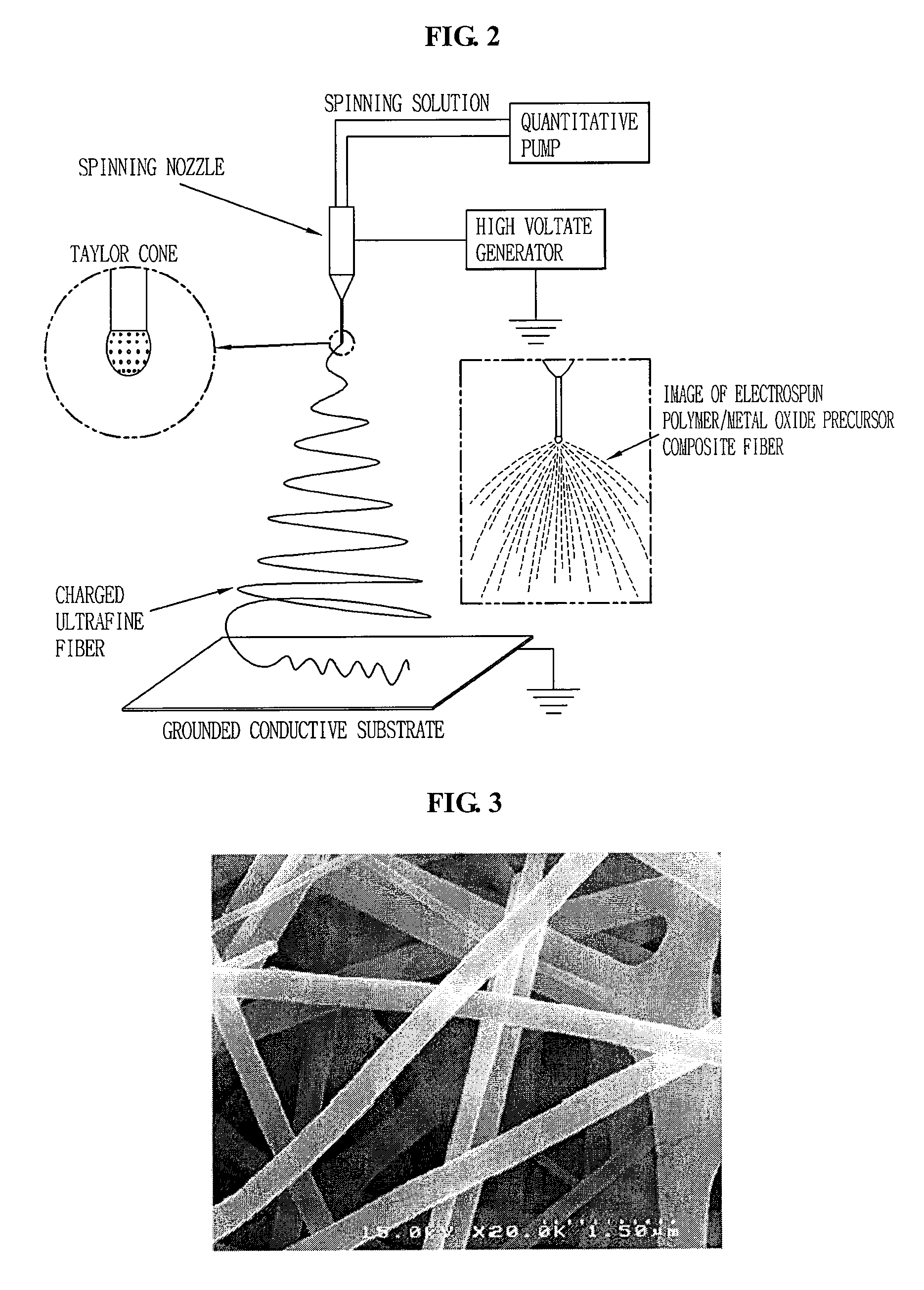
[0068]The transparent precursor in which the reaction had occurred was transferred into a syringe and mounted on the electrospinning device. Then, a voltage was applied between the tip provided at the end of the syringe and a collector to obtain an SnO2-polyvinylacetate composite fiber layer (see FIG. 3). In this case, the voltage was 12 kv, the flow rate was 30 μl / min, the total discharge amount was 500 to 5,000 μl, ...

example 2

Fabrication of an Fe2O3 Nano-Fiber Network Through Thermocompression and Post-Heating Treatment of an Fe2O3-Polyvinyl Alcohol Composite Fiber Layer

[0076]2.5 g of polyvinyl alcohol (PVA, Mw: 88,000) was dissolved by stirring into 20 g of DI water for one day with heat. The PVA solution was mixed with a solution obtained by dissolving 5 g of anhydrous FeCl3 in 15 g of DI water. A transparent deep green solution could be obtained after stirring for several minutes. Then, 2 g of acetic acid and 0.05 g of Cetyltrimethylammonium bromide (CTAB) were added therein and stirred for several minutes. Here, CTAB serves as an additive for facilitating electrospinning by controlling electric charge characteristics of the metal oxide precursor.

[0077]After such prepared solution was transferred into a syringe and electrospun, a light green PVA-FeCl3 organic / inorganic composite fiber could be obtained (applied voltage: 14 kV, flow rate: 10 μl / min, amount of fabricated fiber: 500 μl, substrate: SUS, d...

example 3

Fabrication of a TiO2 Nano-Fiber Network Through Thermocompression and Post-Heating Treatment of a TiO2-Polyvinyl Acetate Composite Fiber Layer

[0083]6 g of titanium propoxide (Titanium(IV) propoxide) was added to be stirred into a polymer solution prepared by dissolving 37.5 ml of a mixed solvent of dimethylformamide (DMF) into 3 g of polyvinyl acetate (Mw: 850,000). Then, 2.4 g of acetic acid was slowly added as a reaction catalyst.

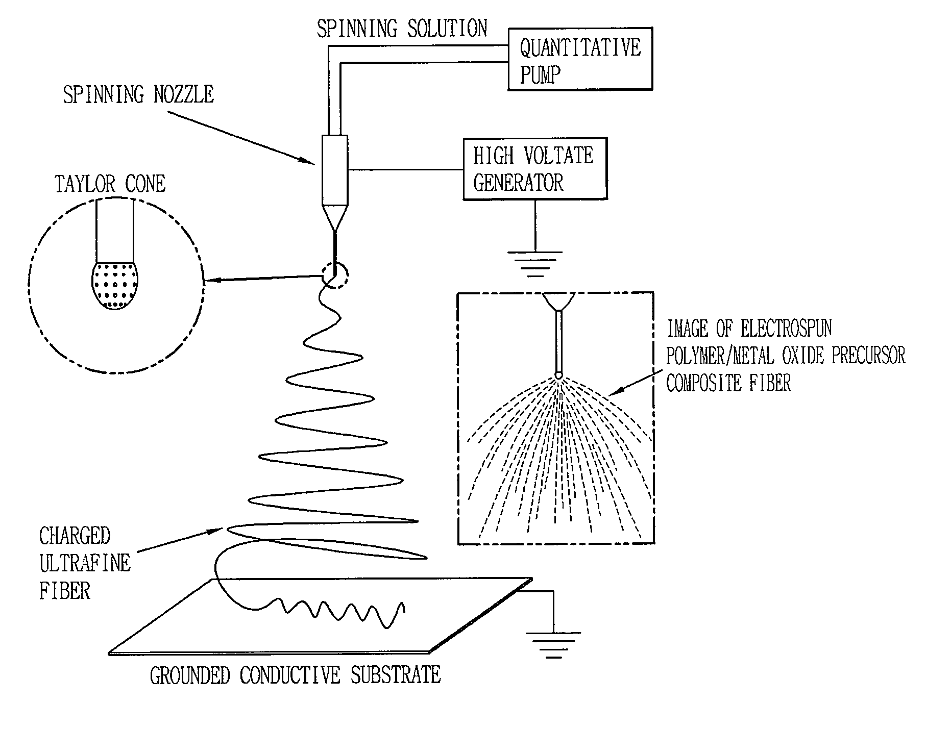
[0084]The electrospinning was carried out by using the electrospinning device in FIG. 1. A stainless steel (SUS) substrate was used as a cathode, and the metal needle connected to the pump controlling the discharge speed was used as an anode. A voltage of 15 kV was applied between the two electrodes. The discharge speed of the spinning solution was controlled to 30 μg / min. The electrospinning was performed until the total discharge amount became 500-5,000 μl, thereby forming an ultrafine TiO2-polyvinyl acetate composite fiber layer on the stainless steel...


PUM

PropertyMeasurementUnit
Temperatureaaaaaaaaaa
Sizeaaaaaaaaaa
Sizeaaaaaaaaaa

Abstract

There is provided a metal oxide having a continuous nano-fiber network structure as a negative active material for a secondary battery. A method for fabricating such negative active material for a secondary battery comprises spinning a mixed solution of a metal oxide precursor and a polymer onto a collector to form composite fibers mixed with the metal oxide precursor and the polymer, thermally compressing or thermally pressurizing the composite fibers, and thermally treating the thermally compressed or thermally pressurized composite fibers to remove the polymer from the composite fiber.

Description

TECHNICAL FIELD[0001]The present invention relates to an anode for a secondary battery having a negative active material with a nano-fiber network structure and a secondary battery using the same, and to a fabrication method of a negative active material for a secondary battery.BACKGROUND ART[0002]Recently, electronic devices (e.g., MP3 players, digital cameras, mobile phones, digital camcorders, PDAs, notebooks, and the like) are being made smaller in size for being more easily carried. With such trend, studies on a secondary battery as a source of power supply capable of being smaller and lighter for being more easily carried and more durable, in particular, a Li-secondary battery, have been steadily progressing. For such source of power supply, if a battery as a thin layer having a thickness of a few tens of nm to a few μm can be integrated inside of a micro device, it can be widely used in various fields such as MEMS (Micro Electro Mechanical System), micro robotics, micro senso...

Claims


Application Information

Patent Timeline
IPC IPC(8): H01M4/02B22F3/11H01M4/04H01M4/131H01M4/1391H01M10/052H01M10/36
CPCB82Y30/00Y10S977/948C04B35/6225C04B35/62254C04B35/62259C04B35/624C04B35/63416C04B2235/3232C04B2235/3256C04B2235/3258C04B2235/3272C04B2235/3275C04B2235/3277C04B2235/3279C04B2235/3281C04B2235/3284C04B2235/3286C04B2235/3293C04B2235/441C04B2235/444C04B2235/449C04B2235/526C04B2235/5264C04B2235/5454D01D5/0007D01F9/10H01M4/0435H01M4/0471H01M4/131H01M4/1391H01M4/661H01M10/052H01M2004/027Y02E60/122C04B35/62231Y02E60/10H01M4/04H01M4/13H01M4/64
Inventor KIM, IL-DOOHONG, JAE-MINJO, SEONG-MU
Owner KOREA INST OF SCI & TECH
Learn More