Film formation method and apparatus for semiconductor process
a film formation and semiconductor technology, applied in the field of film formation apparatus and method for a semiconductor process, can solve the problems of increasing parasitic capacitance, increasing parasitic capacitance a background level, and deteriorating inter-substrat uniformity in the composition of deposited films, so as to improve the uniformity of inter-substrat composition
- Summary
- Abstract
- Description
- Claims
- Application Information
AI Technical Summary
Benefits of technology
Problems solved by technology
Method used
Image
Examples
first embodiment
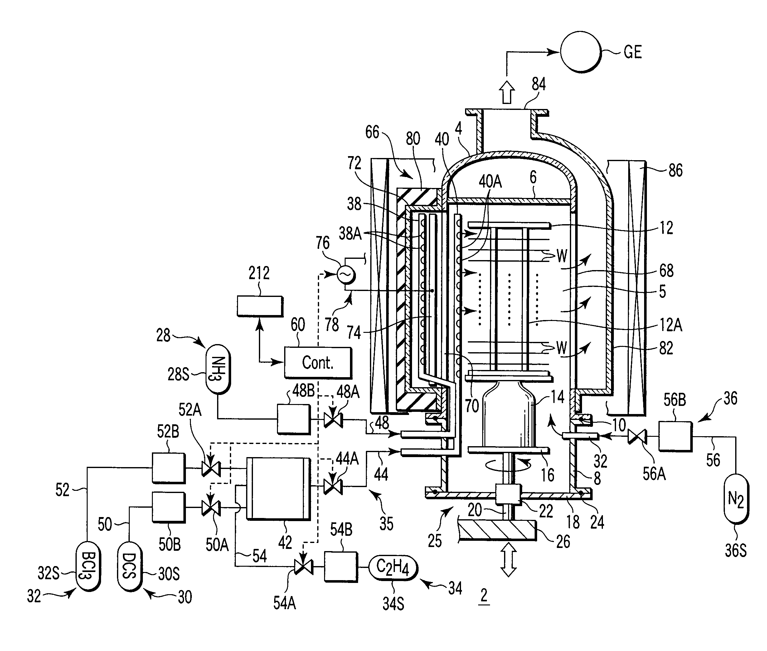
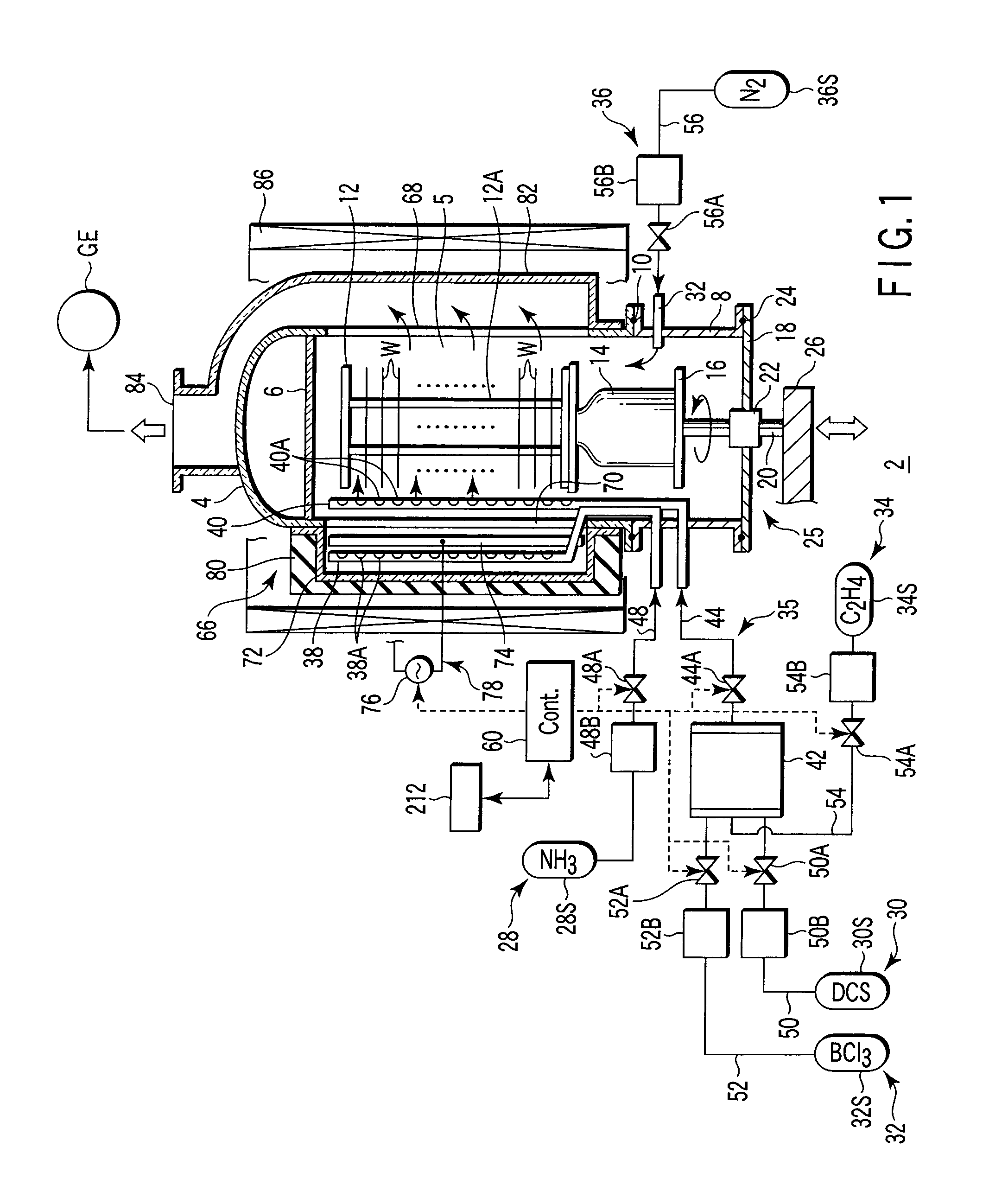
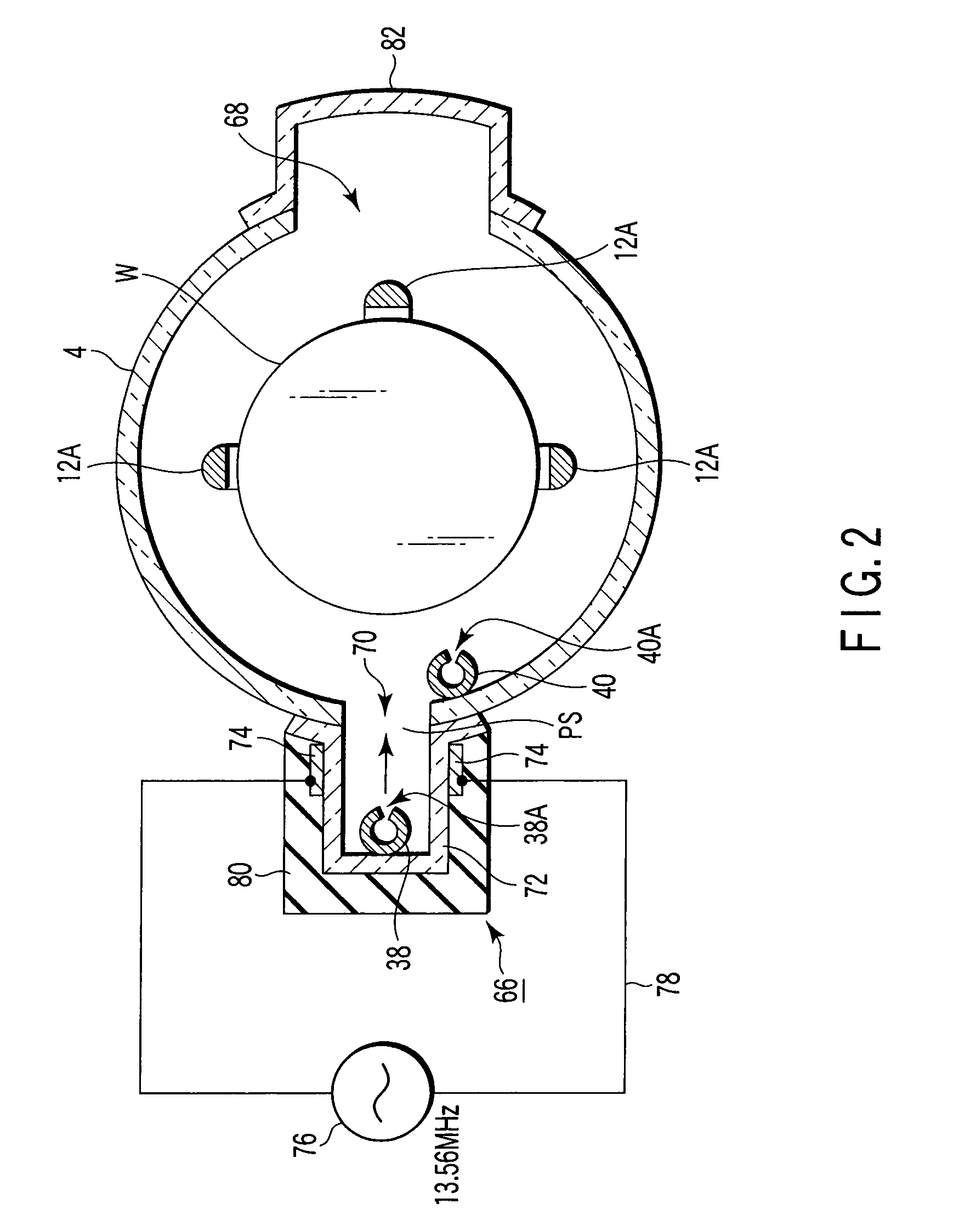
[0083]FIG. 1 is a sectional view showing a film formation apparatus (vertical CVD apparatus) according to a first embodiment of the present invention. FIG. 2 is a sectional plan view showing part of the apparatus shown in FIG. 1. The film formation apparatus 2 has a process field configured to be selectively supplied with a first process gas containing dichlorosilane (DCS) gas as a silane family gas, a second process gas containing ammonia (NH3) gas as a nitriding gas, and a third process gas containing BCl3 gas as a boron-containing gas. The film formation apparatus 2 is configured to form an SiBN (boron doped silicon nitride) film on target substrates by CVD in the process field. Accordingly, the boron-containing gas is used as a doping gas. The process field is further configured to be selectively supplied with a fourth process gas containing C2H4 gas (ethylene gas) as a carbon hydride gas, as needed.
[0084]The apparatus 2 includes a process container 4 shaped as a cylindrical col...
second embodiment
[0123]FIG. 4 is a sectional view showing a film formation apparatus (vertical CVD apparatus) according to a second embodiment of the present invention. This film formation apparatus 2X has the same structure as the film formation apparatus 2 shown in FIG. 1 except for the first, third, and fourth process gas supply circuits 30, 32, and 34 and the mixture gas supply circuit 35. Accordingly, an explanation will be give of the film formation apparatus 2X, focusing on the difference from the film formation apparatus 2.
[0124]In the film formation apparatus 2X, the first, third, and fourth process gas supply circuits 30, 32, and 34 are connected to a common mixture gas supply circuit 35X. The mixture gas supply circuit 35X includes a mixture gas supply pipe 40X configured to mix the first and third process gases, and further the fourth process gas in addition thereto, as needed. The mixture gas supply pipe 40X is formed of a quartz pipe, which is a proximal end portion of a gas distributi...
second embodiments
Common Matters to First and Second Embodiments
[0131]Each of the methods according to the first and second embodiments is performed under the control of the main control section 60 in accordance with a process program, as described above. FIG. 6 is a block diagram schematically showing the structure of the main control section 60. The main control section 60 includes a CPU 210, which is connected to a storage section 212, an input section 214, and an output section 216. The storage section 212 stores process programs and process recipes. The input section 214 includes input devices, such as a keyboard, a pointing device, and a storage media drive, to interact with an operator. The output section 216 outputs control signals for controlling components of the processing apparatus. FIG. 6 also shows a storage medium 218 attached to the computer in a removable state.
[0132]Each of the methods according to the first and second embodiments may be written as program instructions for execution...
PUM
| Property | Measurement | Unit |
|---|---|---|
| diameter | aaaaa | aaaaa |
| volume | aaaaa | aaaaa |
| frequency | aaaaa | aaaaa |
Abstract
Description
Claims
Application Information
 - R&D
- Intellectual Property
- Life Sciences
- Materials
- Tech Scout
- Unparalleled Data Quality
- Higher Quality Content
- 60% Fewer Hallucinations
Browse by: Latest US Patents, China's latest patents, Technical Efficacy Thesaurus, Application Domain, Technology Topic, Popular Technical Reports.
© 2025 PatSnap. All rights reserved.Legal|Privacy policy|Modern Slavery Act Transparency Statement|Sitemap|About US| Contact US: help@patsnap.com


