
Siphon jet toilet

a technology of jet toilet and flushing water, which is applied in water installations, water closets, constructions, etc., can solve the problems of delay in filling, disconnection between the flushing water in the storage tank and the accumulated water in the bowl portion, and achieve the effect of conserving the volume of flushing water used

Inactive Publication Date: 2008-11-06
TOTO LTD
View PDF7 Cites 14 Cited by
  • Summary
  • Abstract
  • Description
  • Claims
  • Application Information

AI Technical Summary

Benefits of technology

[0015]It is therefore an object of the present invention to provide a siphon jet toilet capable of conserving the volume of flush water used for flushing the toilet.
[0016]Another object of the is to provide a siphon jet toilet capable of securing the same or better flushing functionality as conventional products using a smaller volume of flush water than those conventional products.

Problems solved by technology

This type of biasing of the flow rate distribution of flush water spouted from the jet water spout opening 4 results in a delay in filling the drain trap passage, which in turn delays the start of the siphon action.
In this regard, in the toilet pre-flush state (the initial state), the inside of the jet water channel is open to the atmosphere, resulting in a disconnection between the flush water in the storage tank and the accumulated water in the bowl portion.
There is a risk that the presence of air in the jet water channel will buffer the water head pressure in the storage tank and thereby reduce the flow rate of flush water from the jet water spout opening.
A reduced flush water flow rate delays the start of the siphon action, so that flush water is wastefully consumed and the need for water conservation cannot be met.
When the flow rate of the flush water drops, the start of the siphon action is delayed, that portion of flush water is wastefully consumed, and the toilet cannot fulfill the need for water conservation.
Moreover, in the above-described siphon jet toilet in U.S. Pat. No. 7,111,333, there is no head-on collision across essentially the entire area of the two flush waters upon merging as there is in Japanese Utility Model Publication No. 1-44616, and the merging portion is a somewhat larger space, so pressure loss is thought to be ameliorated, but appropriate pressure loss capable of expelling air in the jet water channel in a short time cannot be established with this toilet.

Method used


Image

  • Siphon jet toilet
  • Siphon jet toilet
  • Siphon jet toilet

Examples


Embodiment Construction

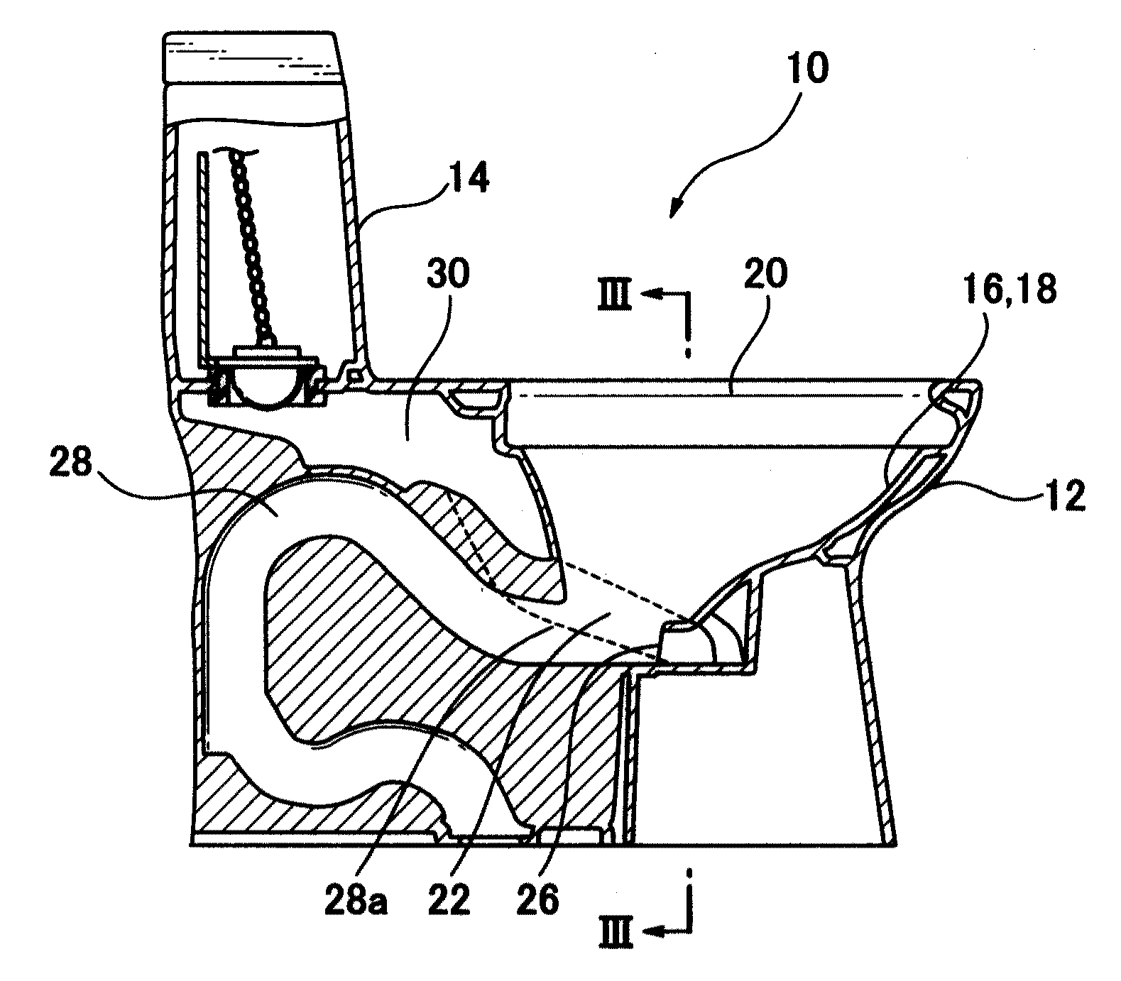
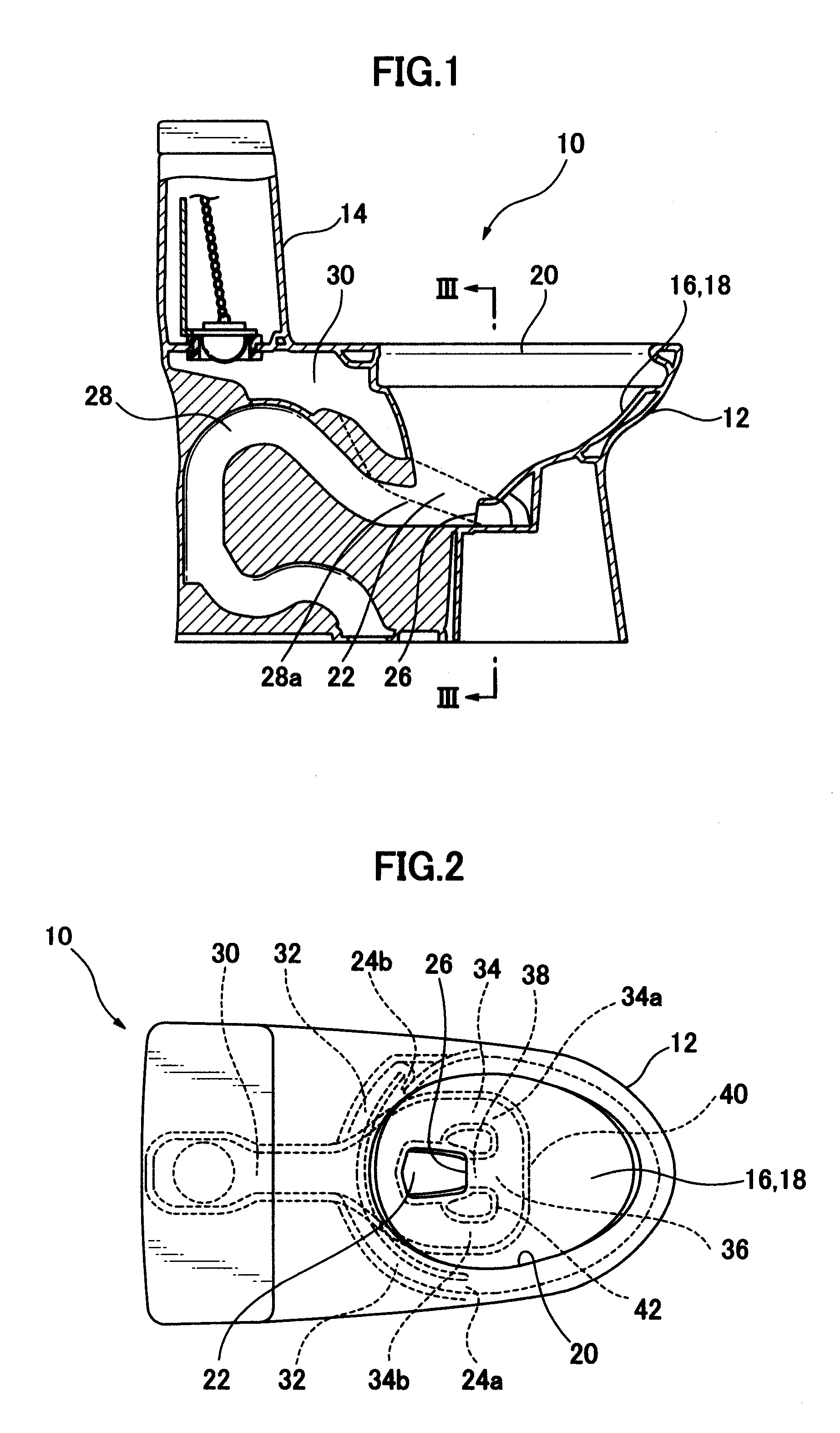
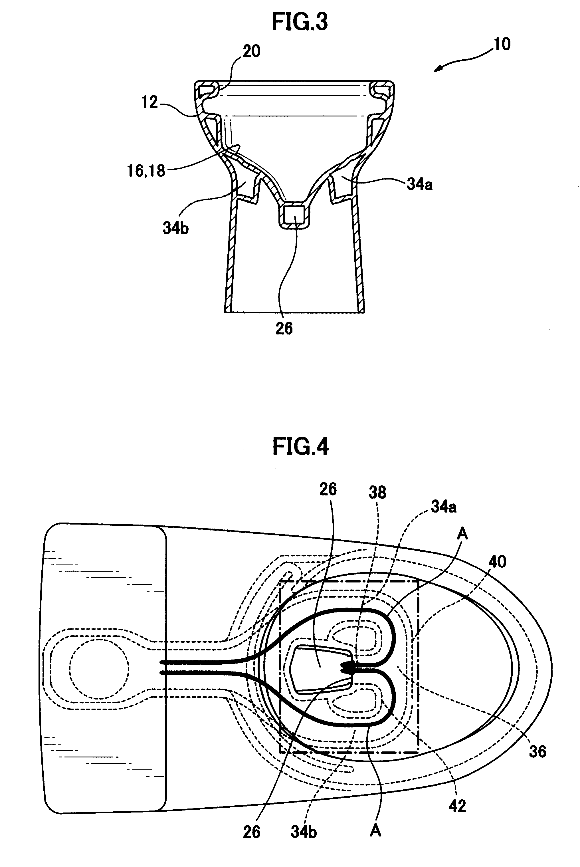
[0041]Next, referring to the attached drawings, a siphon jet toilet according to an embodiment of the present invention will be discussed. First, referring to FIGS. 1 through 3, the basic structure of a siphon jet toilet according to the embodiment of the present invention is discussed. FIG. 1 is a front elevation cross sectional view showing a siphon jet toilet according to the embodiment of the present invention; FIG. 2 is a plan view of FIG. 1, and FIG. 3 is a cross sectional view along line III-III in FIG. 1.

[0042]As shown in FIGS. 1 through 3, the siphon jet toilet 10 according to the embodiment comprises a toilet main unit 12 and a storage tank 14 for storing flush water, disposed at the upper rear portion of the toilet main unit 12. The storage tank 14 stores 2.5 liters to 6.5 liters of flush water.

[0043]The toilet main unit 12 comprises a bowl portion 16 at the front portion thereof; on the bowl portion 16 are formed a bowl-shaped waste-receiving surface 18 and a rim 20, whi...


PUM


Abstract

A siphon jet toilet for supplying flush water in a storage tank by using the head pressure thereof is disclosed. The siphon jet toilet has a toilet main unit furnished with a bowl portion, a rim water spout, a drain trap passage for expelling waste using siphon action, a jet water spout opening formed at a position opposite the inlet of the drain trap passage, a rim water channel for supplying flush water to the rim water spout opening, and a jet water channel for supplying flush water to the jet water channel. The jet water channel includes a plurality of branched water conduits, a merging portion for causing flush water from the plurality of branched water conduits to merge and swirl toward the jet water spout opening and a flow aligner for aligning the flow of flush water merged in the merging portion. The merging portion including an outer wall portion formed in essentially a straight line so that flush waters in the outer region of the swirl collide head-on and an inner wall portion on which a bent portion is formed so that flush water in the inner region of the swirl flows smoothly toward the jet water spout opening.

Description

BACKGROUND OF THE INVENTION[0001]1. Field of the Invention[0002]The present invention relates to a siphon jet toilet, and in particular to a siphon jet toilet for supplying flush water in a storage tank by using the head pressure of flush water.[0003]2. Description of the Related Art[0004]Siphon jet toilets are conventionally known in which flush water is supplied to a jet water spout opening formed on the bowl portion of the main body of a toilet using the head pressure of flush water stored in a storage tank, and waste is expelled to the outside using the siphon action of a drain trap passage. In conventional siphon jet toilets, as shown in FIG. 10, flush water from a storage tank (not shown) is supplied to a jet water spout opening 4 via a jet water channel 2 formed on a bowl portion 1, therefore the jet water channel 2 has a U shape when seen in planar view.[0005]However, when the jet water channel 2 has a U shape, flush water supplied from the jet water channel 2 takes on a swi...

Claims


Application Information

Patent Timeline
IPC IPC(8): E03D11/18
CPCE03D11/08E03D2201/30
Inventor OKADA, TAKASHISHIBATA, SHINJIKAWASAKI
Owner TOTO LTD
Learn More