
Information exchanging apparatus

a technology of information exchange and equipment, applied in electrical equipment, commmunication supplementary services, substation equipment, etc., can solve problems such as the inability to use functions that have not yet become common, and achieve the effect of facilitating information exchange and facilitating coordination

Active Publication Date: 2008-10-30
ROHM CO LTD
View PDF8 Cites 27 Cited by
  • Summary
  • Abstract
  • Description
  • Claims
  • Application Information

AI Technical Summary

Benefits of technology

[0012]In view of the above, it is an object of the present invention to provide an information exchanging apparatus that permits easier information exchange; another object of the invention is to provide an information exchanging apparatus that permits easy coordination among a comparatively large number of people.

Problems solved by technology

Inconveniently, however, with conventional information exchanging apparatuses, because of charges for the use of cellular phone networks, such functions have not yet become common as functions that can be easily used like those, such as games, executed within cellular phones themselves.

Method used


Image

  • Information exchanging apparatus
  • Information exchanging apparatus
  • Information exchanging apparatus

Examples


first embodiment

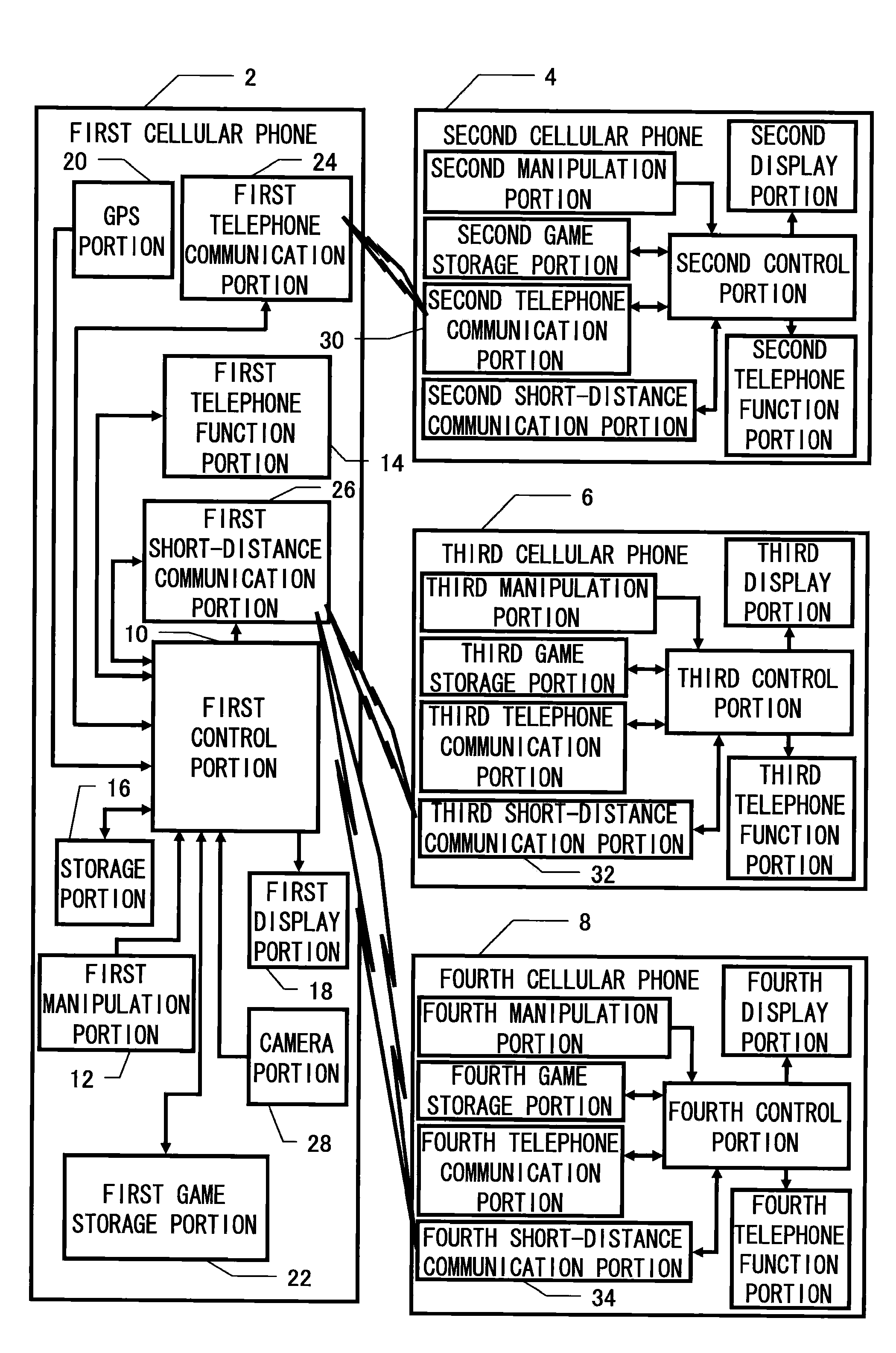
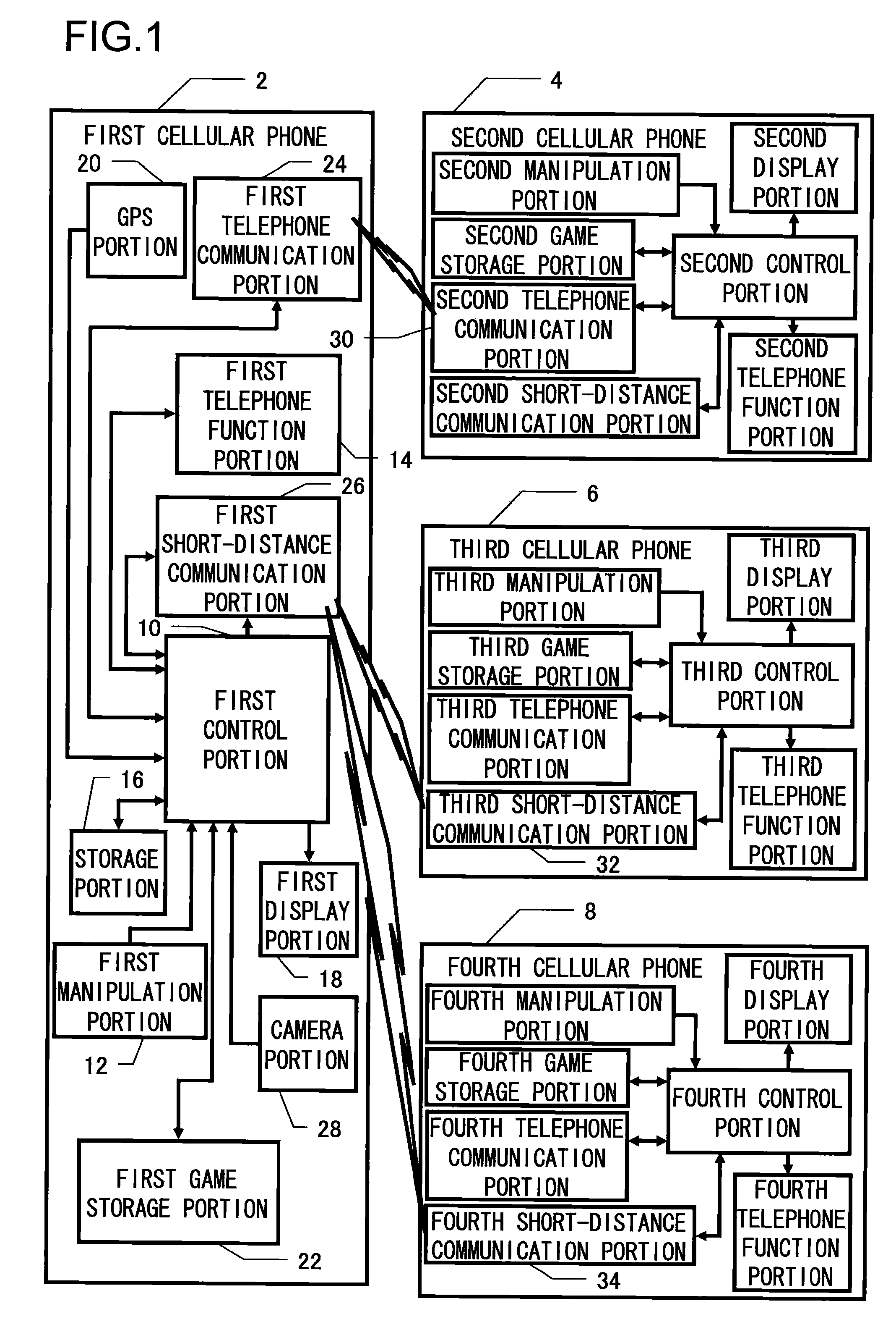
[0034]FIG. 1 is a block diagram showing, as a first embodiment, a game system embodying the invention. This embodiment is built as a cellular phone-based system, which includes a first cellular phone 2, a second cellular phone 4, a third cellular phone 6, and a fourth cellular phone 8. These are basically similarly configured. Although only four cellular phones are shown in FIG. 1, this is for the sake of simplicity: this embodiment is built as a system presupposing a large number of cellular phones, and assumes a system involving about 100 similarly configured cellular phones located within a short-distance communication range.

[0035]The first cellular phone 2 has a first control portion 10 comprising a computer controlling the entire cellular phone, and, according to how a first manipulation portion 12 is operated, the first control portion 10 controls a first telephone function portion 14 etc. The functions of the first control portion 10 are executed by software stored in a stora...

second embodiment

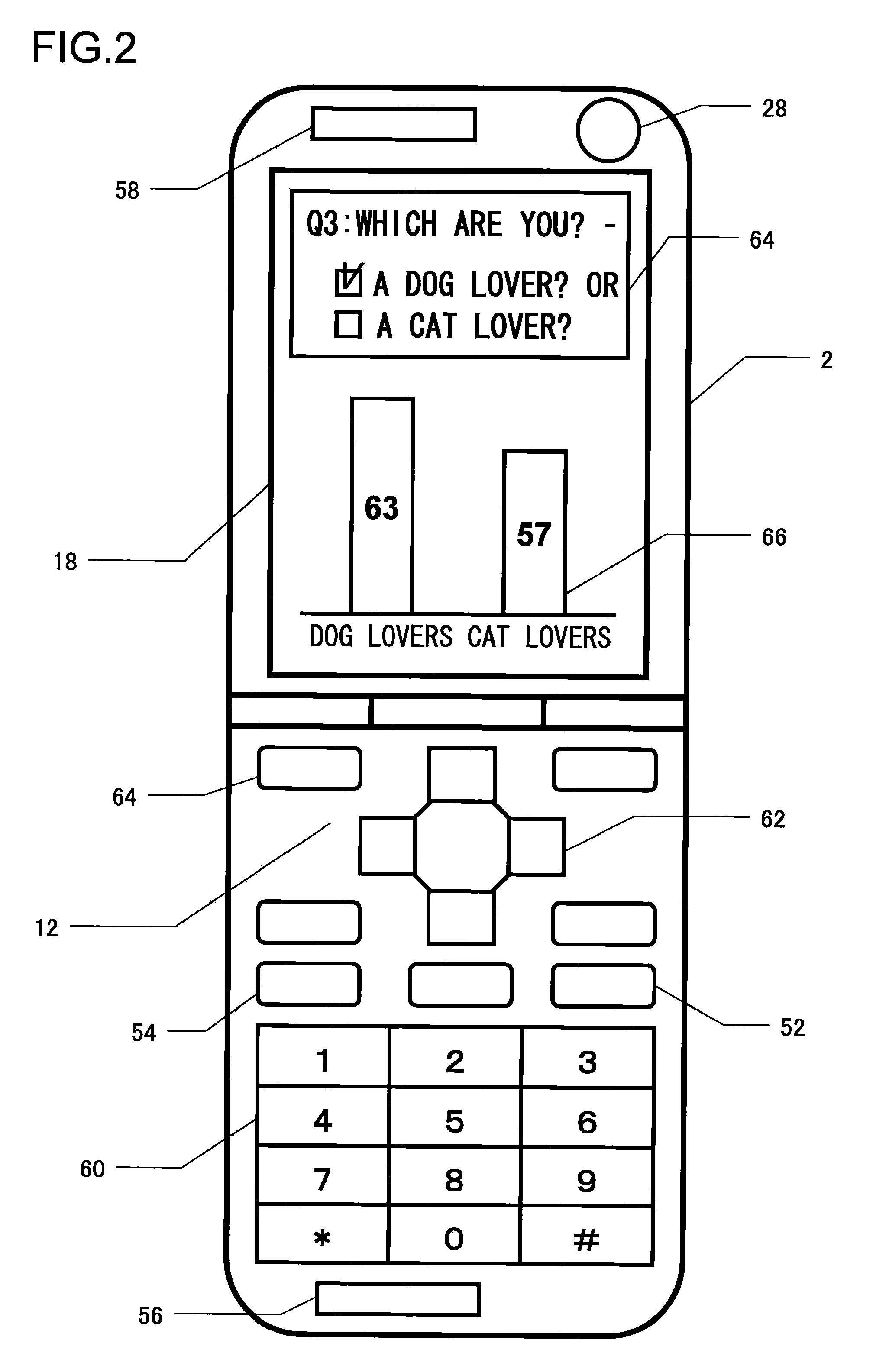
[0061]FIG. 3 shows an example of what is displayed on the first display portion 18 in the second embodiment configured as described above when the owner of the first cellular phone 2 visits the locality. In the query area 72, a visitor property input column 74 is provided. If sure that there is no privacy risk, the visitor, by operating the cross-shaped keys 62 etc., checks, in the visitor property input column 74, one of the check boxes for different residence zones, one of the check boxes for different sexes, and one of the check boxes for different age groups. The data of these visitor properties is made use of mainly in the management of the sightseeing area. In the query area 72, a popular spot voting column 76 is also provided, where the visitor, by operating the numerical keys 60 etc., inputs, out of sightseeing spot numbers assigned on a map of the sightseeing area, the one assigned to the sightseeing spot that the visitor has most liked.

[0062]In an information presentation ...


PUM


Abstract

An information exchanging apparatus capable of exchanging information with a plurality of outside apparatuses has: a first wireless communicator including a telephone transmitter and telephone receiver for wireless telephone communication with one of the outside apparatuses; a second wireless communicator other than the first wireless communicator; a transmitter arranged to transmit original information to the plurality of outside apparatuses through the second wireless communicator; a processor arranged to process response information from the plurality of outside apparatuses to be received through the second wireless communicator in response to the original information; and a distributor arranged to distribute result information from the processor to the plurality of outside apparatuses through the second wireless communicator.

Description

[0001]This application is based on the following Japanese Patent Applications, the contents of which are hereby incorporated by reference:[0002](1) Japanese Patent Application No. 2007-119252 (filed on Apr. 27, 2007)[0003](2) Japanese Patent Application No. 2007-124218 (filed on May 9, 2007)[0004](3) Japanese Patent Application No. 2007-125753 (filed on May 10, 2007)[0005](4) Japanese Patent Application No. 2007-128289 (filed on May 14, 2007)[0006](5) Japanese Patent Application No. 2007-130613 (filed on May 16, 2007)BACKGROUND OF THE INVENTION[0007]1. Field of the Invention[0008]The present invention relates to an information exchanging apparatus utilizing wireless communication.[0009]2. Description of Related Art[0010]Cellular phones are one of typical information exchanging apparatuses utilizing wireless communication. Various proposals have been made to use cellular phones for the purposes of conducting information exchange other than voice communication. For example, JP-A-2001-...

Claims


Application Information

Patent Timeline
IPC IPC(8): H04B1/38H04M1/00H04M1/72412H04M1/72427
CPCH04M1/72544H04M1/7253H04W4/16H04M1/72427H04M1/72412H04M11/00H04B7/26
Inventor TANAKA, MASAHIDE
Owner ROHM CO LTD
Learn More