Eureka AIR delivers breakthrough ideas for toughest innovation challenges, trusted by R&D personnel around the world.

Amplification Relay Device of Electromagnetic Wave and a Radio Electric Power Conversion Apparatus Using the Above Device

a relay device and electromagnetic wave technology, applied in the field of amplifier repeaters, can solve the problems of inability to obtain energy according to wireless power conversion, inability to install, and large installation position restrictions, so as to increase the induced electromotive force, increase the flux linkage, and increase the effect of flux

Active Publication Date: 2008-10-30
JC PROTEK +1
View PDF3 Cites 339 Cited by
  • Summary
  • Abstract
  • Description
  • Claims
  • Application Information

AI Technical Summary

Benefits of technology

"The present invention relates to an amplifying repeater that can increase the induced electromotive force of electromagnetic waves using a ferrite core and a coil with a predetermined number of winds. The repeater can be connected to a wireless power converter to effectively transmit the induced power. The invention also provides a construction for measuring the charging voltage, current, and power using the repeater and the wireless power converter. The technical effects of the invention include increasing the current and reducing the resistive component in the induction coil, intensifying and amplifying the magnetic field of electromagnetic waves, and unrestricted installation of the amplifying repeater."

Problems solved by technology

Thus, the induced electromotive force is hardly induced to the induction coil at more than a predetermined distance so that energy according to wireless power conversion cannot be obtained.
Furthermore, the induction coil must be disposed within a very short range from the electromagnetic wave generating source in a prior art so that its installation position is greatly restricted or it cannot be installed because of its bad appearance.

Method used

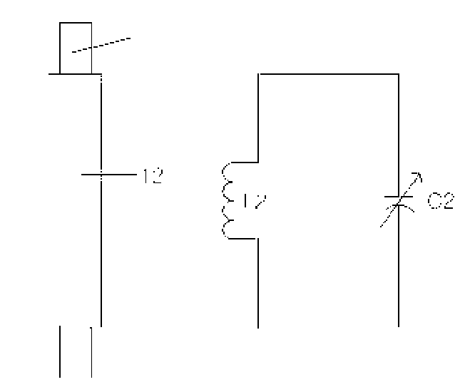
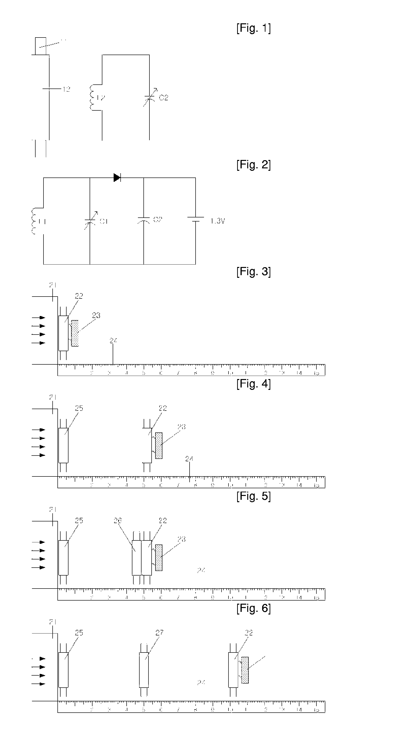
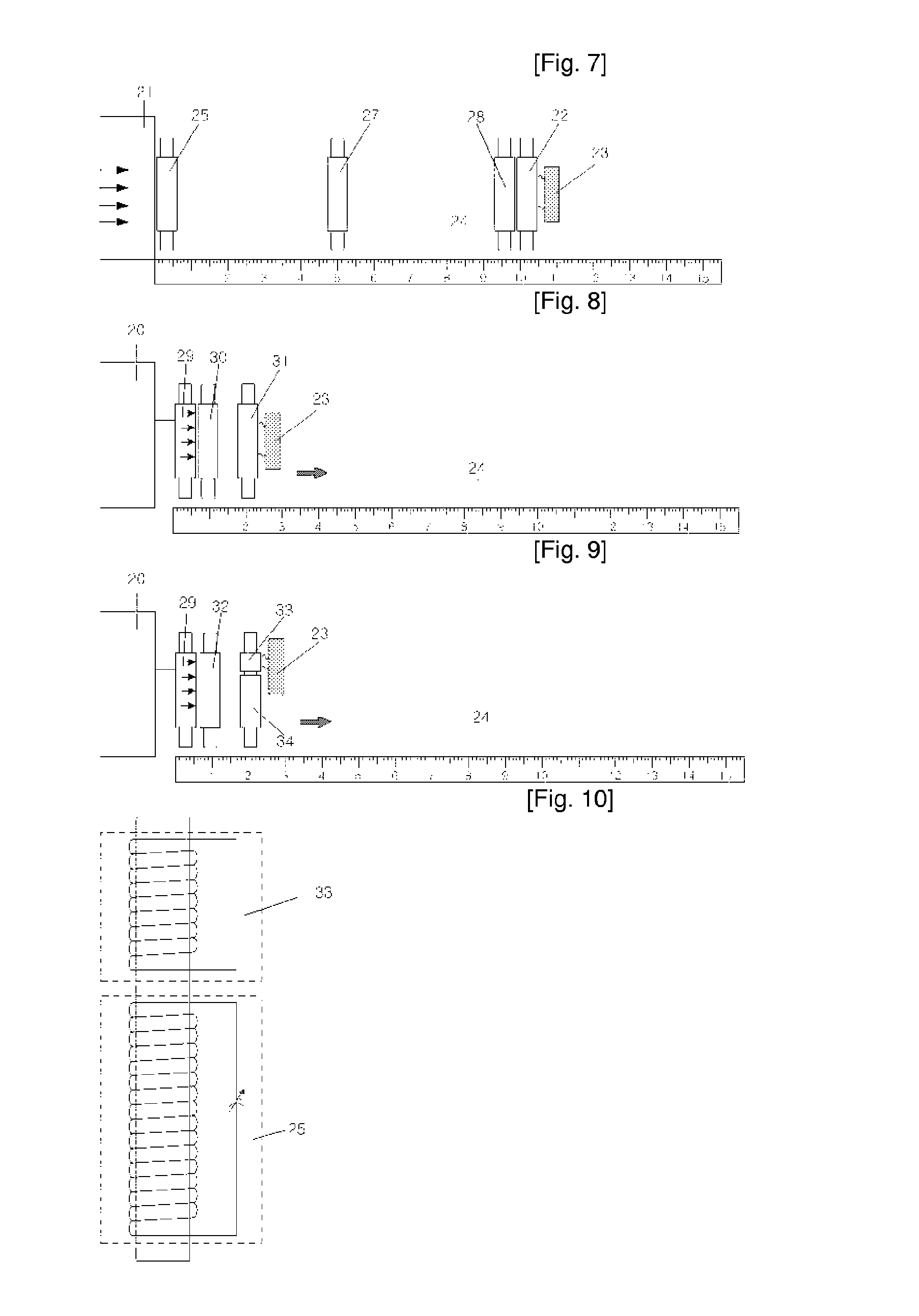

Image

  • Amplification Relay Device of Electromagnetic Wave and a Radio Electric Power Conversion Apparatus Using the Above Device
  • Amplification Relay Device of Electromagnetic Wave and a Radio Electric Power Conversion Apparatus Using the Above Device
  • Amplification Relay Device of Electromagnetic Wave and a Radio Electric Power Conversion Apparatus Using the Above Device

Examples


Embodiment Construction

[0035]The present invention will now be described in detail in connection with preferred embodiments with reference to the accompanying drawings. For reference, like reference characters designate corresponding parts throughout several views.

[0036]The present invention provides an amplifying repeater, which is constructed in such a manner that a ferrite core is inserted into a coil with a predetermined number of winds to increase an induced electromotive force caused by an increase in flux linkage using a time-varying magnetic field of electromagnetic waves using Faraday's law at a position distant from an electromagnetic wave generating source by a predetermined distance and the induction coil and a variable condenser for inducing resonance are connected to each other to maximize an induced current while reducing a resistant component existing in the induction coil to amplify the magnetic field of electromagnetic waves. Furthermore, the present invention provides a wireless power c...


PUM

PropertyMeasurementUnit
external diameteraaaaaaaaaa
diameteraaaaaaaaaa

Abstract

The present invention provides an amplifying repeater, which is constructed in such a manner that a ferrite core is inserted into a coil with a pre-determined number of winds to increase an induced electromotive force caused by an increase in flux linkage using a time-varying magnetic field of electromagnetic waves at a position distant from various electromagnetic wave generating sources by a predetermined distance and the induction coil and a variable condenser for inducing resonance are connected to each other to increase current while reducing a resistant component existing in the induction coil to intensify and amplify the magnetic field of electromagnetic waves. Furthermore, the present invention provides a wireless power conversion charging device using the magnetic field of electromagnetic waves, which is located between an electromagnetic wave generating source transmitter and a receiving coil or attached to the transmitter and receiving coil. The wireless power conversion charging device includes a rectifying diode for rectifying an electromotive force induced in a construction in which a resonance and impedance matching variable condenser is connected to a coil in series or in parallel in order to transmit maximum induced power to a charging battery that is a load using electromagnetic waves amplified by the amplifying repeater, and a smoothing condenser for smoothing the rectified voltage. Accordingly, charging power required for various small power electronic devices can be provided and power can be supplied to various loads.

Description

TECHNICAL FIELD[0001]The present invention relates to an amplifying repeater, which is constructed in such a manner that a ferrite core is inserted into a coil with a predetermined number of winds to increase an induced electromotive force caused by an increase in flux linkage using a time-varying magnetic field of electromagnetic waves at a position distant from an electromagnetic wave generating source by a predetermined distance, and that the coil and a variable condenser for inducing resonance are connected to each other to intensify and amplify the magnetic field of electromagnetic waves, and a wireless power converter using electromagnetic waves, which is located at a predetermined distance from the amplifying repeater, connects a resonance and impedance matching variable condenser to a coil to effectively transmit an induced power to a load, and rectifies and smoothes the induced power using a diode to supply the power to a charging battery or various loads.BACKGROUND ART[000...

Claims


Application Information

Patent Timeline
Patent Type & Authority Applications(United States)
IPC IPC(8): H03H7/01H01F38/00H04B7/14H04B5/48H04B7/155
CPCH02J5/005H02J7/025H04B7/15535H01F38/14H04B5/0037H02J7/00712H02J50/502H02J50/12H04B5/79H04B7/14
Inventor LEE, HYUNG-JOO
Owner JC PROTEK
Why Eureka
Eureka Blog
Learn More