
Cursor control device and method for an image display, and image system

Inactive Publication Date: 2008-10-30
PIXART IMAGING INC
View PDF20 Cites 24 Cited by
  • Summary
  • Abstract
  • Description
  • Claims
  • Application Information

AI Technical Summary

Benefits of technology

[0007]It is an object of the present invention to provide a cursor control device and a cursor control method for an image display, wherein the motion of a cursor on the image display can be controlled in two ways by means of a switching mechanism thereby increasing the practicability of the image display.
[0008]It is another object of the present invention to provide an image system which combines two control ways in a single cursor control device so as to simplify the system structure and decrease the cost thereof.
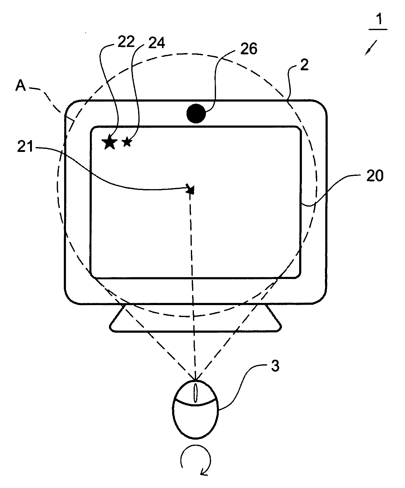
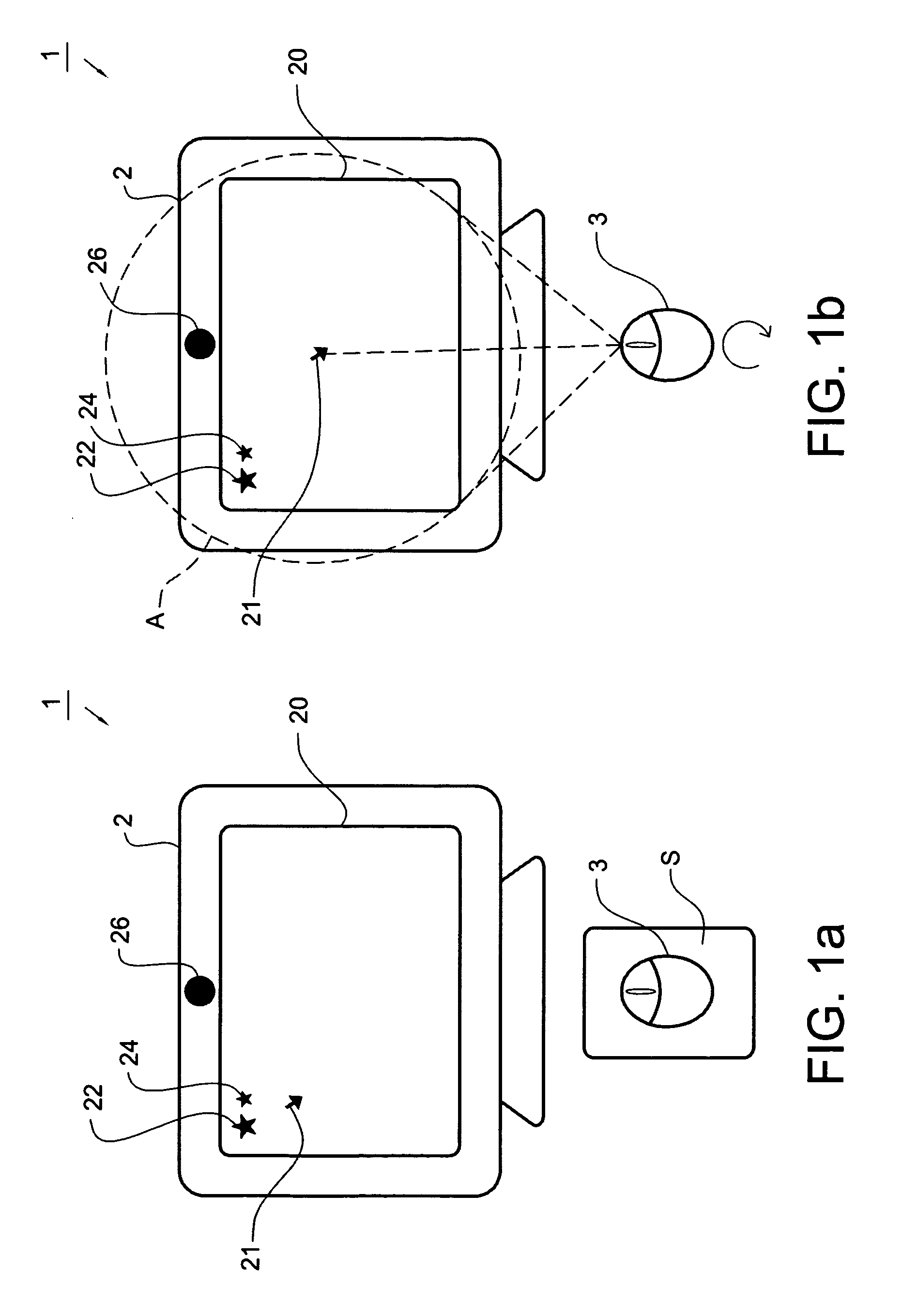
[0010]According to another aspect of the present invention, the present invent further provides an image system including an image display, at least one object, a cursor control device and a coordinate processor. The image display has a screen for displaying image pictures with a cursor shown thereon. The cursor control device includes a first sensing unit for detecting a first displacement of the cursor control device with respect to a surface and calculating a first coordinate variation of the cursor according to the first displacement; a second sensing unit for sensing the object, detecting a second displacement of the cursor control device with respect to the object and calculating a second coordinate variation of the cursor according to the second displacement; a switching device for switching output between the first coordinate variation and the second coordinate variation; and a communication interface unit for transmitting the first or the second coordinate variation selected to be outputted by the switching device. The coordinate processor receives the first or the second coordinate variation from the communication interface unit and combines the first or the second coordinate variation with the coordinate of the cursor shown on the image display such that the cursor control device can accordingly control the motion of the cursor on the screen.

Problems solved by technology

However in practical use, purchasing another pointer positioning device will not only increase the cost, but also has the problem of storage when the pointer positioning device is unused.

Method used


Image

  • Cursor control device and method for an image display, and image system
  • Cursor control device and method for an image display, and image system
  • Cursor control device and method for an image display, and image system

Examples


first embodiment

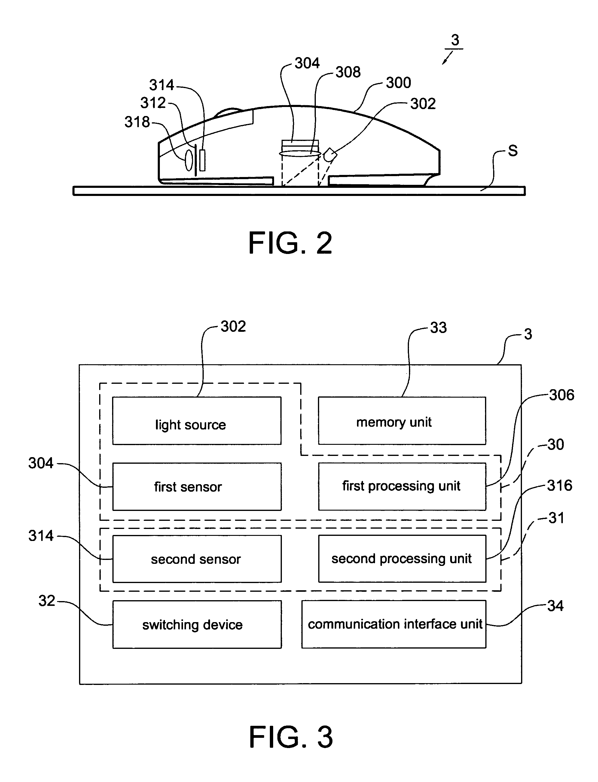
[0035]Referring to FIGS. 2 and 3, they respectively show a schematic view and a block diagram of the cursor control device 3 according to the present invention. The cursor control device 3 includes a house 300; a first sensing unit 30, a second sensing unit 31, a switching device 32, a memory unit 33 and a communication interface unit 34 are disposed inside the house 300. The first sensing unit 30 is for detecting a first displacement of the cursor control device 3 with respect to the surface S and calculating a first coordinate variation of the cursor 21 according to the first displacement. The first coordinate variation will then be electrically (through wire) or wirelessly transmitted to the coordinate processor through the communication interface unit 34 to be combined with the coordinate of the cursor 21 on the screen 20 so as to accordingly control the displaying and setting of the image display 2. The second sensing unit 31 is for sensing the objects 22 and 24 or the object 2...

second embodiment

[0049]Referring to FIG. 11, it shows the cursor control method for the image display 2 according to the present invention. The method includes the following steps: utilizing the first sensing unit 30 to detect a first displacement of the cursor control device 3 with respect to the surface S and to calculate a first coordinate variation of the cursor 21 on the image display 2 according to the first displacement; utilizing the second sensing unit 31 to sense the objects 22 and 24 or the object 26, to detect a second displacement of the cursor control device 3 with respect to the objects 22 and 24 or the object 26, and to calculate a second coordinate variation of the cursor 21 on the image display 2 according to the second displacement; and outputting the first coordinate variation or the second coordinate variation from the cursor control device; wherein a method to determine whether to output the first coordinate variation or the second coordinate variation is by analyzing sensed im...


PUM


Abstract

A cursor control device for an image display includes a first sensing unit, a second sensing unit and a switching device. The first sensing unit is for detecting a first displacement of the cursor control device with respect to a surface and calculating a first coordinate variation of a cursor on the image display according to the first displacement. The second sensing unit is for sensing an object, detecting a second displacement of the cursor control device with respect to the object and calculating a second coordinate variation of the cursor on the image display according to the second displacement. The switching device switches output between the first coordinate variation and the second coordinate variation. The present invention further provides an image system and a cursor control method for an image display.

Description

CROSS REFERENCE TO RELATED APPLICATION[0001]This application claims the priority benefit of Taiwan Patent Application Serial Number 096114378, filed on Apr. 24, 2007, the full disclosure of which is incorporated herein by reference.BACKGROUND OF THE INVENTION[0002]1. Field of the Invention[0003]This invention generally relates to a cursor control device and a cursor control method for an image display; and an image system, which can implement the control of a cursor on an image display in two ways by utilizing a switching mechanism.[0004]2. Description of the Related Art[0005]In a conventional image display, e.g. a computer screen, the motion of a cursor shown on the image display can be accordingly controlled according to a displacement of an optical navigation sensor, e.g. a mouse, on a surface, wherein the displacement is determined by capturing images at different time with the optical navigation sensor and by comparing the relativities of the images captured at different time. ...

Claims


Application Information

Patent Timeline
IPC IPC(8): G06F3/033
CPCG06F3/0304G06F3/0312G06F3/0317G06F3/03542G06F3/03543
Inventor CHAO, TZU YICHEN, HSIN CHIA
Owner PIXART IMAGING INC
Learn More