Hand Drying Apparatus
- Summary
- Abstract
- Description
- Claims
- Application Information
AI Technical Summary
Benefits of technology
Problems solved by technology
Method used
Image

Examples
first embodiment
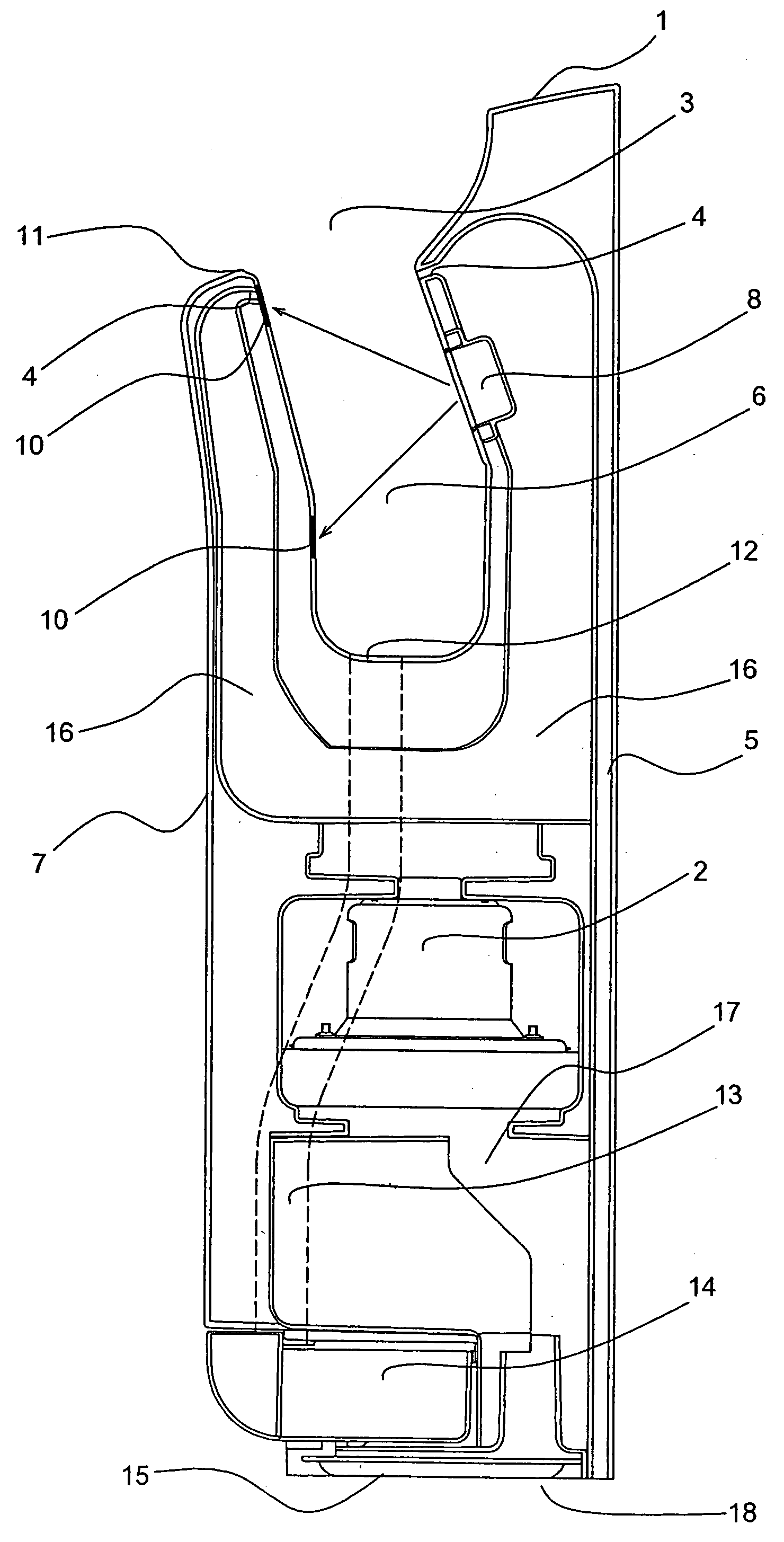
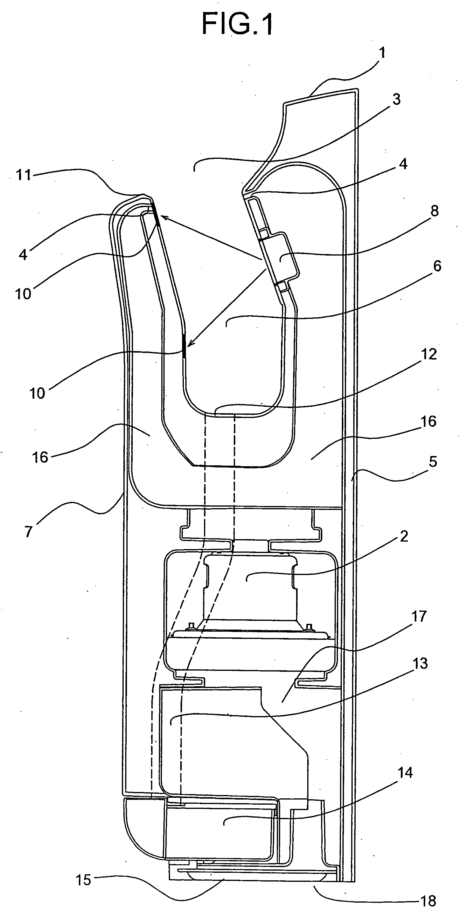
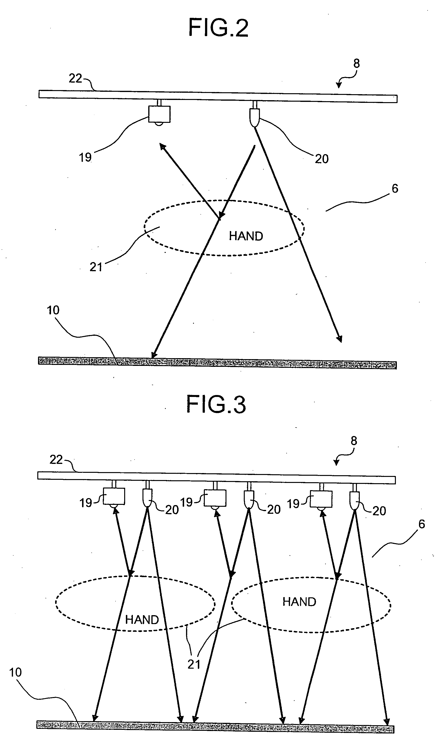
[0037]A hand drying apparatus according to a first embodiment of the present invention will be explained with reference to FIG. 1 to FIG. 3. FIG. 1 is a right side cross-section of a hand drying apparatus according to the first embodiment. FIGS. 2 and 3 are plan views of parts of a hand detector.
[0038]As shown in FIG. 1, the hand drying apparatus has a main unit box member 1 constituted of a base 5 forming a rear face outer shell and a front panel 7 forming a front face outer shell. A recessed space serving as a hand insertion portion 3 and a drying space 6 is formed on an upper side of the main unit box member 1. The recessed space is formed in an open sink shape with both sides opened and hands can be inserted.
[0039]A high pressure airflow generator 2 is assembled in the main unit box member 1, and a high pressure airflow generated by the high pressure airflow generator 2 is guided to air nozzles 4 provided on a front side wall face and a rear side wall face around the hand insert...
second embodiment
[0055]A hand drying apparatus of a second embodiment of the present invention will be explained next with reference to FIG. 5. In the second embodiment, the hand detector 8 constituted of the infrared light emitter 20 and the infrared light receiver 19 is arranged on the rear face side in the drying space 6 and an infrared light emitter 9 is provided at a front position opposed to the infrared light receiver 19 of the hand detector 8, and hands inserted near the hand insertion portion 3 in the drying space 6 is detected by a reflection type constitution including the infrared light emitter 20 and the infrared light receiver 19 built in the hand detector 8, while hands inserted into deeper in the drying space 6 is detected by a transmission type constitution including the infrared light emitter 9 and the infrared light receiver 19. Infrared rays A and B emitted from the infrared light emitter 20 and the infrared light emitter 9 and received by the infrared light receiver 19 can be di...
PUM
 Abstract
Description
Claims
Application Information
 - R&D
- Intellectual Property
- Life Sciences
- Materials
- Tech Scout
- Unparalleled Data Quality
- Higher Quality Content
- 60% Fewer Hallucinations
Browse by: Latest US Patents, China's latest patents, Technical Efficacy Thesaurus, Application Domain, Technology Topic, Popular Technical Reports.
© 2025 PatSnap. All rights reserved.Legal|Privacy policy|Modern Slavery Act Transparency Statement|Sitemap|About US| Contact US: help@patsnap.com