Telescoping ramp

Active Publication Date: 2008-10-30
RADIO SYST
View PDF20 Cites 12 Cited by
  • Summary
  • Abstract
  • Description
  • Claims
  • Application Information

AI Technical Summary

Benefits of technology

[0007]It is an object of the present invention to provide a telescoping ramp that can be easily used and transported.
[0008]It is a further object of the present invention to provide a telescoping ramp that can be easily deployed.
[0011]It is yet a further object of the present invention to provide a telescoping ramp that is portable, sturdy, lightweight, adjustable and aesthetically pleasing.
[0018]In the preferred embodiment, the telescoping ramp includes a mounting extension on the first, outer ramp member. The mounting extension is attached to the lateral side of the planar surface that will extend out and adjoins the first, outer ramp member at an obtuse angle relative to the surface of the outer ramp member. The mounting extension may be attached at a predetermined angle to facilitate use of the telescoping ramp between surfaces having different elevations, such as between the ground and the back of an automobile. The mounting extension may be fitted with one or more protrusions, such as non-skid pegs, on its bottom surface to prevent the ramp from slipping off the desired elevated surface.
[0019]The telescoping ramp may also include a mounting extension adjoining the second ramp member. The “lower” mounting extension is attached to the planar surface of the inner ramp member at the lateral side closest to the lower elevated surface upon which the ramp will be placed. Similar to the “higher” mounting extension, the lower extension is attached at an obtuse angle relative to an upper side of the planar surface of the second ramp member and may include one or more non-skid protruding members to prevent the ramp from slipping on the lower surface.
[0025]As with the previous embodiment, this embodiment of the telescoping ramp may also include mounting extensions adjoining the ramp members to facilitate use of the ramp of surfaces having different elevations. The structure and alignment of the mounting extensions are similar to those of the embodiment described above. Similarly, non-skid members may also be added to prevent the ramp from slipping during use.

Problems solved by technology

However, the angular supports disclosed by the Gewirtz reference are not supported other than through their being integrated to the load bearing surface of the runners with no lateral support from the sides of the runners.
The Gewirtz ramp lacks structural support at the angular support members and its integrated structure makes it difficult to construct out of light weight materials.
The angular deployment of its tracks on one of its runners makes it susceptible to collapse when heavier objects or animals are placed on the ramp in its extended state.

Method used


Image

  • Telescoping ramp
  • Telescoping ramp
  • Telescoping ramp

Examples


Embodiment Construction

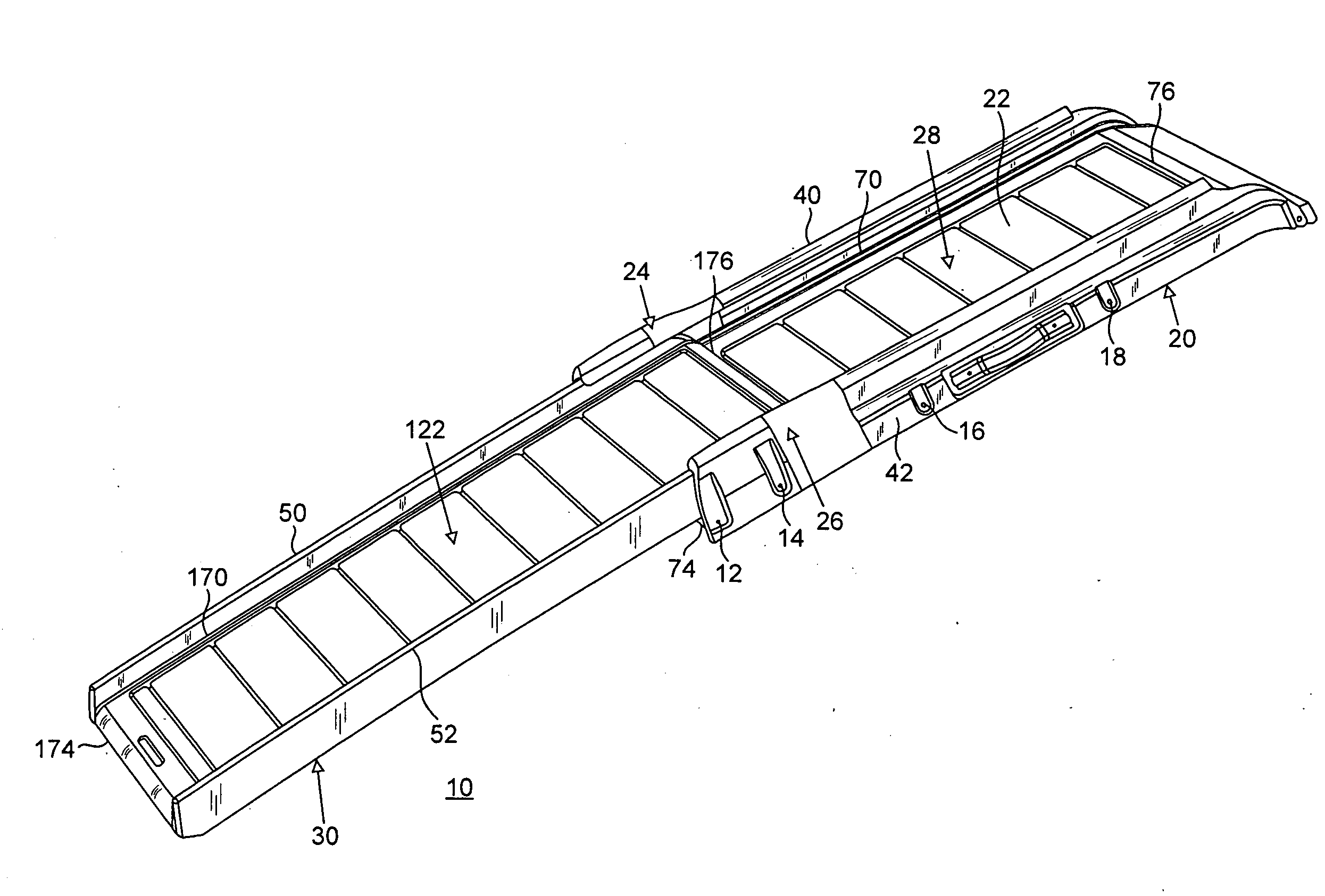
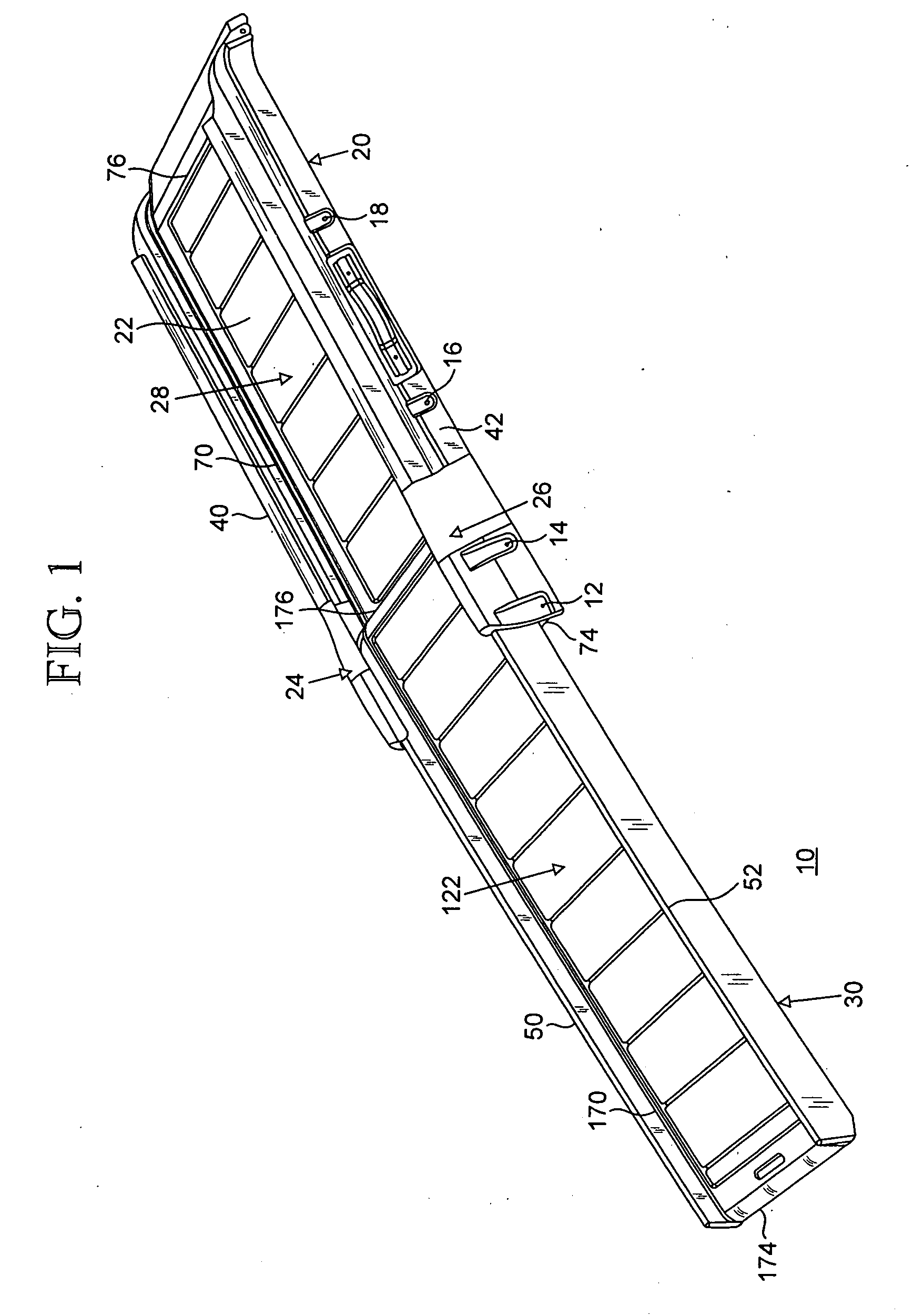
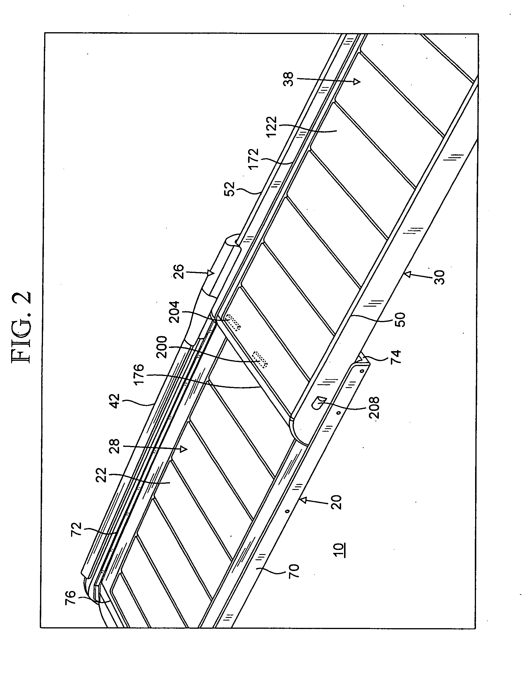
[0048]The present invention relates to a telescoping ramp 10, and more particularly, a portable, lightweight, adjustable and telescoping ramp used to connect a short span, especially spans of different elevations. It is important to note that the embodiments of the invention described below are only examples of some of the uses of the teachings described herein. In general, statements made in the specification do not limit any of the various claimed inventions. Moreover, some statements may apply to some inventive features but not to others. Unless otherwise indicated, singular elements may be in the plural and vice versa with no loss of generality. Similar reference numerals and letters represent similar components and system features throughout the drawings and the written description.

[0049]FIGS. 1 through 7 illustrate one exemplary embodiment of the telescoping ramp 10 of the present invention. FIGS. 8 through 10 illustrate another exemplary embodiment of the telescoping ramp. FI...


PUM


Abstract

The present invention includes a telescoping ramp that includes two ramp members that fit one atop the other such that the two members may be extended out or collapsed together. The first, outer ramp member has channels on either side of a substantially planar surface. The channels of the outer ramp member are structured to capture the rails on either side of a second ramp member. An inverted J-shaped channel is formed along each of the longitudinally aligned sides of the first ramp member. One embodiment includes inverted J-shaped channels that are dimensionally larger near the side that engages the other ramp member. The second ramp member is sized to between the inverted J-shaped channels and includes protruding rail-like members formed along each of its longitudinally aligned sides. The protruding members are complementarily shaped to slide and fit within a corresponding inverted J-shaped channel of the first ramp member.

Description

CROSS-REFERENCE TO RELATED APPLICATIONS[0001]The present application claims priority to U.S. provisional patent application No. 60 / 782,475 filed Mar. 13, 2006. The entire disclosure of U.S. provisional patent application No. 60 / 782,475 is incorporated herein by reference.FIELD OF THE INVENTION[0002]The present invention relates to a telescoping ramp, and more particularly, a portable, lightweight, adjustable and telescoping ramp which can be used to make traversing a short span easier.BACKGROUND OF THE INVENTION[0003]Many have created ramps, including telescoping ramps, that can be used for a multitude of purposes. For example, U.S. Pat. No. 5,244,335 to Johns discloses a telescopic tailgate ramp for the back of a pickup truck. Similarly, U.S. Pat. No. 5,813,071 to Breslin, et al., discloses a telescopic truck loading ramp assembly to facilitate the loading and unloading of a truck.[0004]U.S. Pat. No. 6,345,950 to Gewirtz discloses a ramp assembly for spanning between two surfaces. ...

Claims


Application Information

Patent Timeline
IPC IPC(8): B65G69/30B65G69/28
CPCB65G69/30
Inventor HOFFMAN, PATRICK
Owner RADIO SYST
Why Eureka
Try Eureka