
Nailing machine

a technology of nailing machine and stapling rod, which is applied in the field of nailing machines, can solve the problems of affecting workability and deteriorating the end and achieve the effects of reducing the length of the most compressed spring, constant elastic energy, and reducing the length of the nailing spring

Active Publication Date: 2008-10-23
HITACHI KOKI CO LTD
View PDF8 Cites 42 Cited by
  • Summary
  • Abstract
  • Description
  • Claims
  • Application Information

AI Technical Summary

Benefits of technology

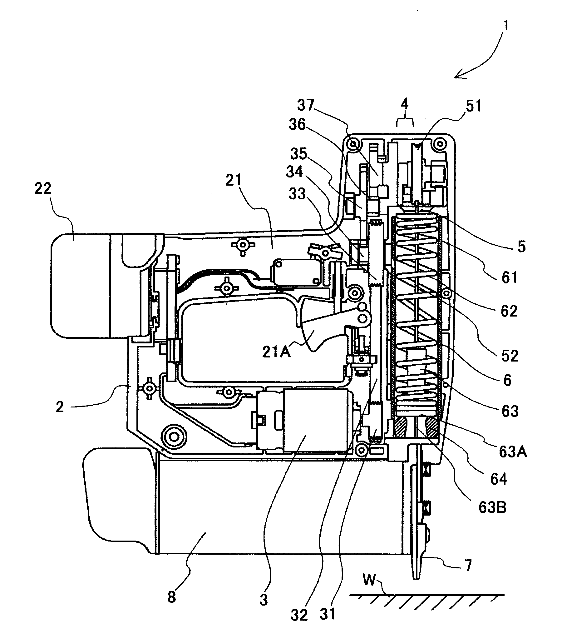
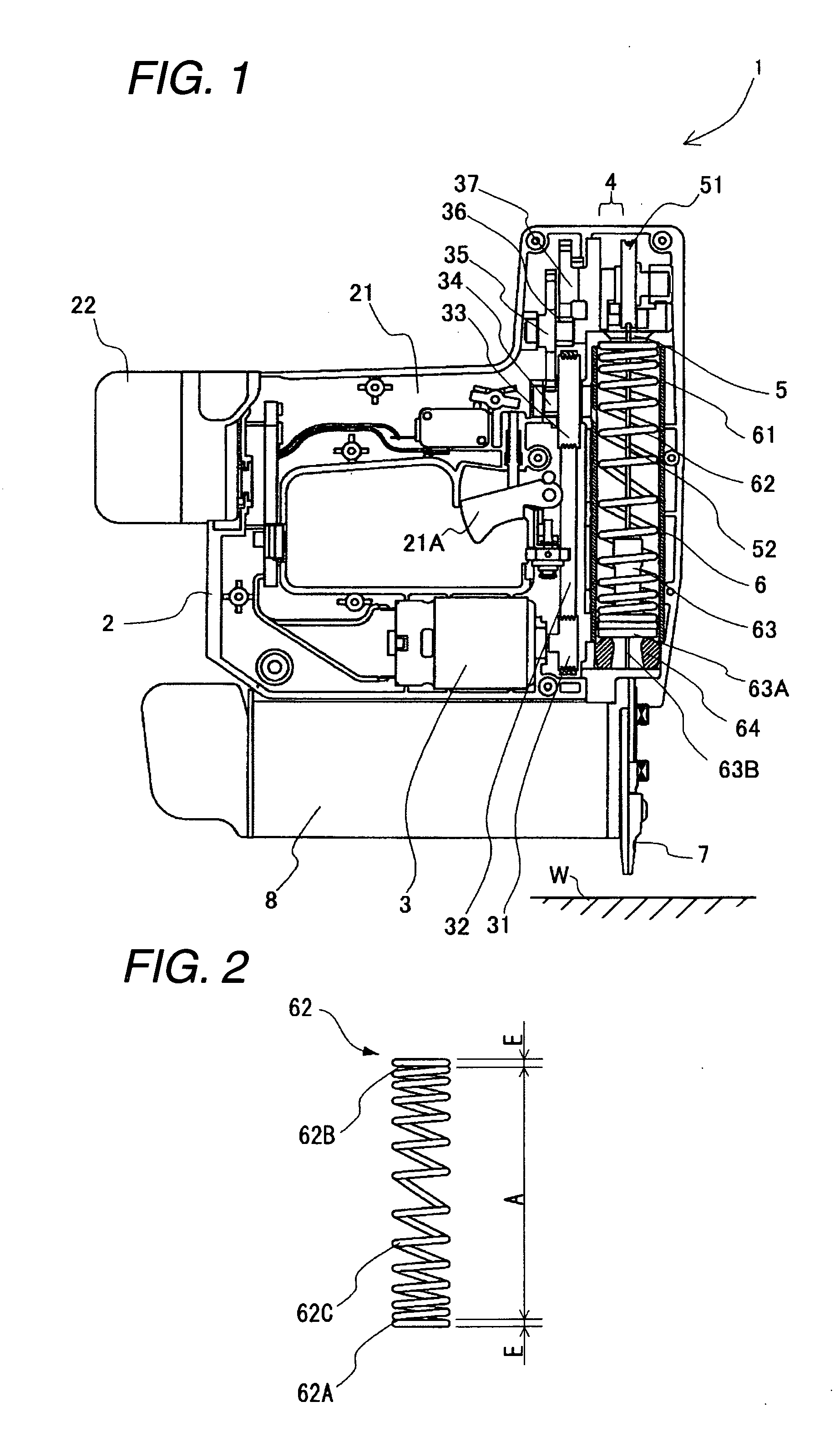
[0010]According to the above-mentioned configuration, since the spring constant of the ends of the spring is small, the ends of the spring can be easily expanded and compressed. Accordingly, even when an impact is applied to the ends of the spring, it is possible to easily absorb the impact. As a result, it is possible to improve the durability of the ends of the spring against the expansion and compression. Since the center portion of the spring has a great spring constant, it is possible to accumulate the elastic energy required for the hitting of the plunger. Accordingly, the hitting can be suitably performed without using a large spring, thereby accomplish a decrease in size of the nailing machine.
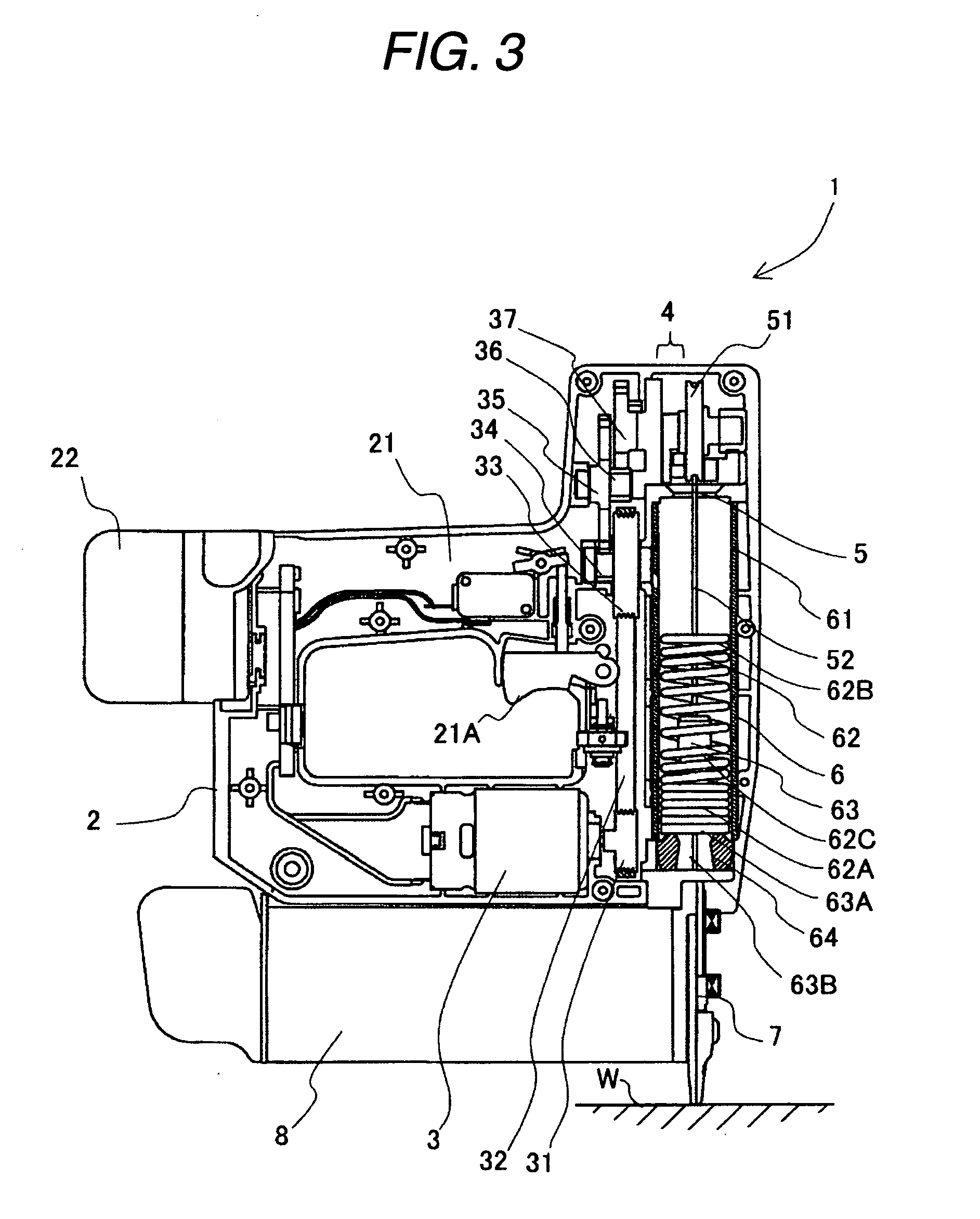
[0013]According to the above-mentioned configuration, in the spring accumulating constant elastic energy, it is possible to reduce the length of the most compressed spring. Accordingly, since it is possible to reduce the length of the spring, it is possible to reduce the size of the nailing machine.

Problems solved by technology

Therefore, the nailing spring might be deteriorated from the ends.
However, in this case, the nailing machine increases in size, the spring constant is enhanced, and the hitting power becomes too strong, thereby damaging the workability.

Method used


Image

  • Nailing machine
  • Nailing machine
  • Nailing machine

Examples


Embodiment Construction

[0019]Hereinafter, a nailing machine according to an embodiment of the invention will be described with reference to FIGS. 1 to 4. A nailer 1 which is a nailing machine shown in FIG. 1 is of an electromotive type and is used to insert a nail, which is a fixing member not shown, into a target member W such as timber and plaster. The nailer 1 roughly includes a housing 2, a motor 3, a clutch mechanism 4, a transmission portion 5, a coil spring portion 6, a nose portion 7, and a magazine 8. In the following description, a direction in which a plunger 63 described later moves is defined as a vertical direction and a direction in which the plunger 63 is urged by a coil spring 62 of the coil spring portion 6 described later to hit a nail not shown is defined as a downward direction.

[0020]The housing 2 is made of resin such as nylon and polycarbonate and has the motor 3 built therein. A handle 21 is disposed in an upper portion of the housing 2 and a trigger 21A controlling the motor 3 is ...


PUM


Abstract

According to an aspect of the present invention, there is provided a nailing machine including: a housing; a motor that is accommodated in the housing; a plunger that plunges a nailing member; and a spring that is expanded or compressed by the motor to store an elastic energy therein and that accelerates the plunger by releasing the elastic energy, wherein a spring constant of the spring at one end of the spring in an expanding / compressing direction is set smaller than that of the spring at a center in the expanding / compressing direction.

Description

CROSS-REFERENCE TO RELATED APPLICATIONS[0001]This application is based upon and claims a priority from prior Japanese Patent Application No. 2007-109066 filed on Apr. 18, 2007, the entire contents of which are incorporated herein by reference.BACKGROUND OF THE INVENTION[0002]1. Field of the Invention[0003]An aspect of the present invention relates to a nailing machine.[0004]2. Description of the Related Art[0005]Spring-driven nailing machines pushing up a plunger, which is urged by a nailing spring, against the urging force of the nailing spring to a top dead center, accelerating the plunger by opening the nailing spring, and driving a nail into a target member with the plunger have already been produced. In the nailing machines, the labor for pushing up the plunger is reduced by pushing the plunger by the use of the motor built in the housing. Specifically, as described in JP-9-295283-A, plural rotating gears coupled to the motor with a reduction gear therebetween are disposed oppo...

Claims


Application Information

Patent Timeline
IPC IPC(8): B25C7/00
CPCB25C1/06B25C5/15
Inventor TANIMOTO, HIDEYUKIODA, HIROYUKINAKANO, YOSHIHIROUEDA, TAKASHI
Owner HITACHI KOKI CO LTD
Learn More