Display Device

a display device and display screen technology, applied in the field of display devices, can solve the problems of insufficient high resolution for image reading operation, etc., and achieve low image display operation and high image reading operation directivity, high display quality, and low resolution

Inactive Publication Date: 2008-10-16
SHARP KK
View PDF7 Cites 8 Cited by
  • Summary
  • Abstract
  • Description
  • Claims
  • Application Information

AI Technical Summary

Benefits of technology

[0052]A display apparatus according to the present invention includes a directivity adjusting section for adjusting the directivity of light which is output from the light output section. Owing to this, the directivity of the light can be set low for an image display operation and high in an image reading operation. Therefore, the image reading operation can be performed without decreasing the resolution while maintaining the high display quality.
[0053]A plurality of pixel sections included in the display apparatus according to the present invention are divided into a plurality of groups. The light output section outputs first light and the light receiving section receives the reflected light on a group-by-group basis. By selecting a plurality of pixel sections for an image reading operation at the time, the time for image reading can be shortened. In a structure where the pixel sections belonging to the same group are discretely located from each other, the phenomenon that the light receiving section of one pixel section receives the reflected light corresponding to the light output from another pixel section can be suppressed. This prevents the resolution of the obtained image from decreasing.

Problems solved by technology

The image input / output device 500 involves a problem that a sufficiently high resolution is not obtained for an image reading operation due to the low directivity of the light which is output from the light emitting element 502a. FIG. 17 shows an image reading operation of the image input / output device 500.
Therefore, there arises the problem that a sufficiently high resolution is not obtained for the image reading operation.
Such a problem occurs also in the case of the display devices disclosed by patent documents 2 and 3 in a similar manner. FIG. 19 shows light which is output from the liquid crystal cell 660.
As a result, there arises the problem that a sufficiently high resolution is not obtained for the image reading operation.

Method used


Image

  • Display Device
  • Display Device
  • Display Device

Examples


embodiment 1

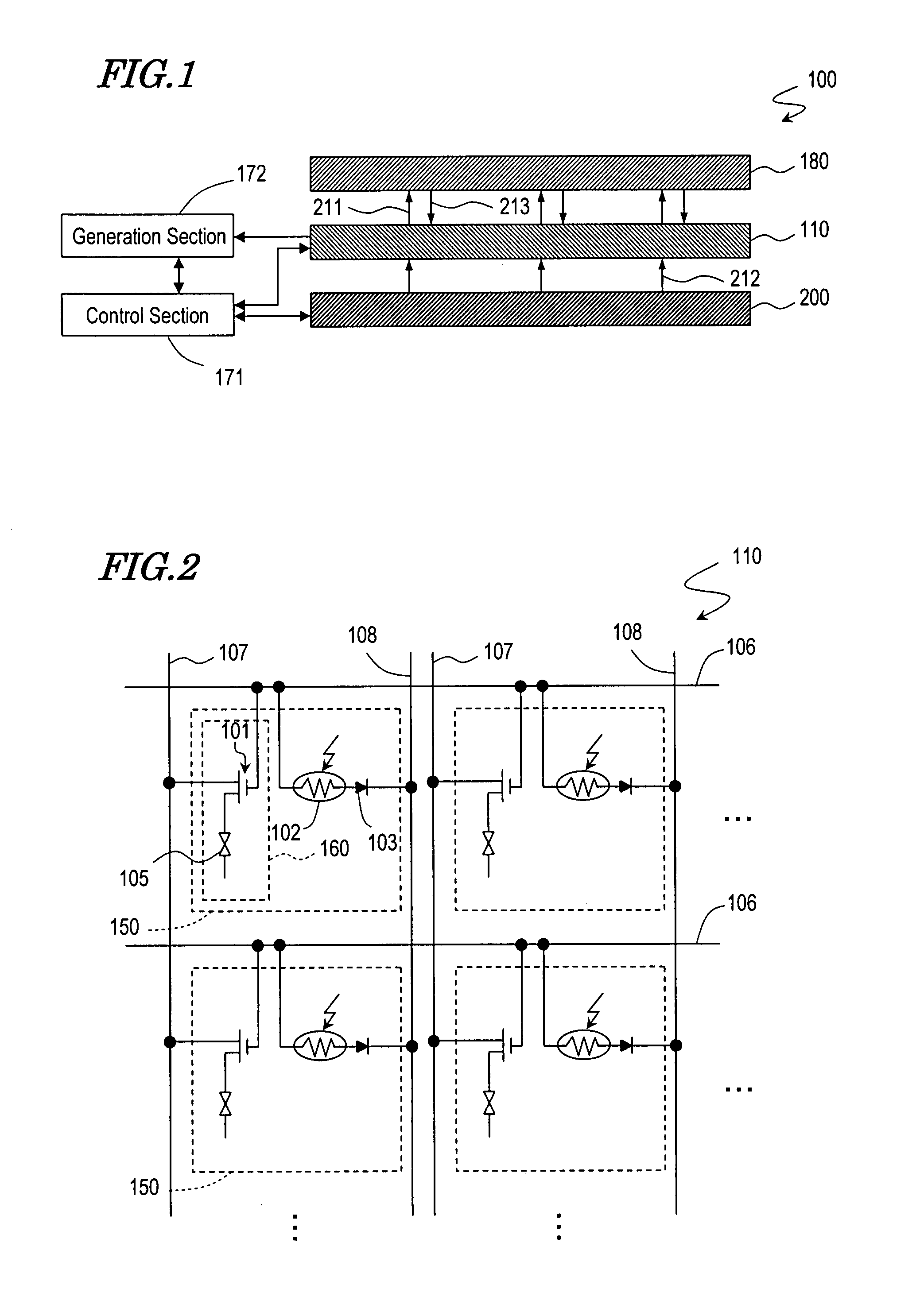
[0098]FIG. 1 schematically shows a liquid crystal display apparatus 100 according to Embodiment 1 of the present invention. The liquid crystal display apparatus 100 performs an image display operation and an image reading operation. The liquid crystal display apparatus 100 includes a liquid crystal display panel 110, an illumination device 200, a control section 171, and a generation section 172. For an image reading operation, an imaging subject 180 (document sheet, photo, business card, etc.) is placed on the liquid crystal display panel 110 with a printing face thereof facing the liquid crystal display panel 110. The control section 171 controls an operation of the liquid crystal display panel 110 and the illumination device 200. For an image reading operation, the generation section 172 generates image information (color gradation pattern of the imaging subject 180 based on the intensity of received light.

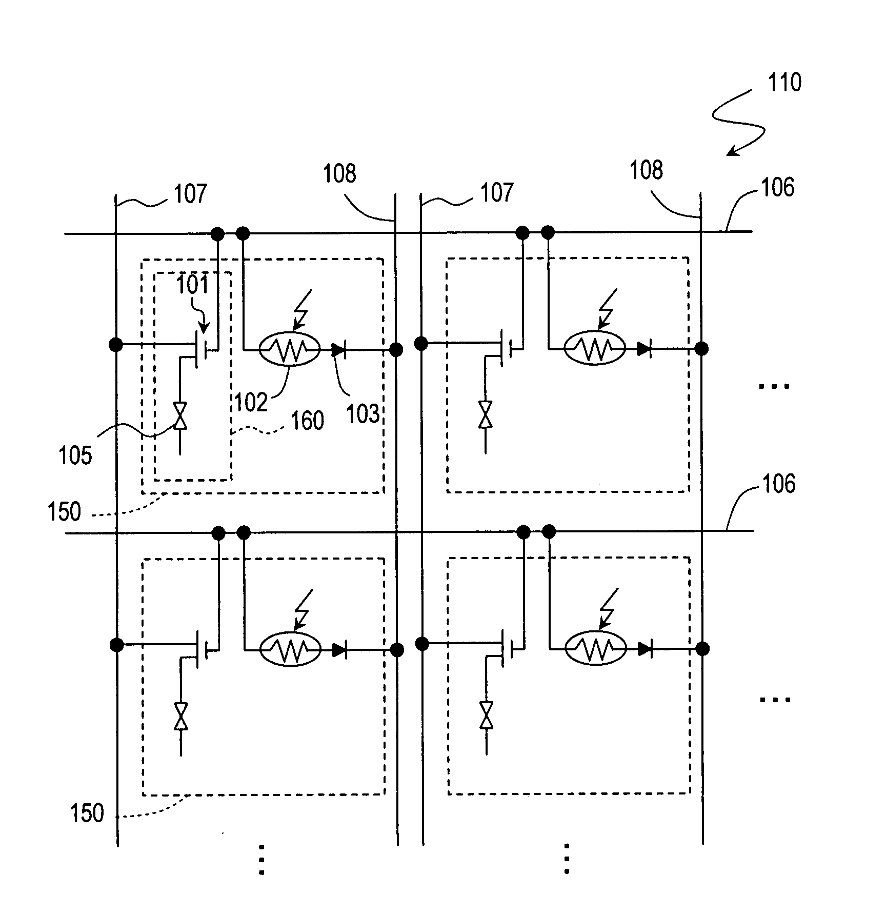
[0099]FIG. 2 schematically shows the liquid crystal display panel 110. The...

embodiment 2

[0133]In Embodiment 1, in the image reading operation, the pixel sections 150 are selected one by one in the image reading operation. This is time-consuming. In this embodiment, in order to shorten the time for reading an image in the image reading operation, a plurality of pixel sections 150 are selected at the same time. When light is output from adjacent pixel sections 150 at the same time, the possibility that the thin film light sensor 102 of one of the pixel sections 150 receives reflected light corresponding to the light output from the other pixel section 150 is high. In this embodiment, all the pixel sections 150 are divided into a plurality of groups such that each group includes a plurality of pixel sections 150 discretely located. For example, a plurality of pixel sections 150 located one pixel section apart, or two pixel sections apart, in a row direction and / or a column direction are grouped. Pixel sections 150 adjacent to each other belong to different groups. For an ...


PUM


Abstract

A display apparatus according to the present invention comprises a plurality of pixel sections 150 and performs an image display operation and an image reading operation. The plurality of pixel sections 150 each include a light output section 160 for outputting first light, and a light receiving section 102 for receiving reflected light obtained as a result of an imaging subject being irradiated with the first light. The apparatus further comprises a directivity adjusting section for adjusting a directivity of the first light. The plurality of pixel sections 150 are divided into a plurality of groups. The light output section 160 outputs the first light and the light receiving section 102 receives the reflected light on a group-by-group basis.

Description

TECHNICAL FIELD[0001]The present invention relates to a display apparatus for performing an image reading operation as well as an image display operation.BACKGROUND ART[0002]Some display devices for performing an image display operation and an image reading operation have been proposed (see patent documents 1 through 4).[0003]An image input / output device disclosed by patent document 1 includes an image input / output panel, in which a plurality of light emitting element / light receiving element pairs located in a matrix on a plane. The light emitting elements act as display elements. For performing an image display operation, the light emitting elements are driven based on image information. An image reading operation is performed as follows. First, a sheet of paper on which color gradation information of letters or the like is recorded is placed on the image input / output panel, such that the surface having the information faces the image input / output panel. The light emitting elements...

Claims


Application Information

Patent Timeline
Patent Type & Authority Applications(United States)
IPC IPC(8): H04N1/024
CPCG02F1/1362G02F2001/13312G09G3/3648G09G2300/0486G09G2320/028H04N1/00347H04N1/02472H04N1/195H04N2201/0063H04N2201/0081H04N2201/0089G02F1/13312
Inventor KATO, HIROMIIZUMI, YOSHIHIRO
Owner SHARP KK
Why Eureka
Try Eureka