
Method, a Program and a Module to Estimate a Doppler Maximum Frequency and an Oscillator Frequency Offset, Receiver Including the Module

a technology of maximum frequency and oscillator, applied in the field of method, a program and a module to estimate a maximum frequency and/or an oscillator frequency offset, and a receiver including the module, can solve the problems of significant degradation of the overall performance of the receiver, local oscillator drift, etc., and achieve precise fd and f0 estimation and reduce noise

Inactive Publication Date: 2008-10-16
ST ERICSSON SA
View PDF5 Cites 11 Cited by
  • Summary
  • Abstract
  • Description
  • Claims
  • Application Information

AI Technical Summary

Benefits of technology

[0020]Accordingly, it is an object of the invention to provide an fd estimation method which is more robust to oscillator frequency offset.
[0030]The above embodiments of the fd estimation method present the following advantage:
[0037]Computing the power density spectrum does not require measurements of phase variations between consecutive pilot symbols, so that this method of estimating offset f0 is simpler and faster.
[0042]The above embodiments of the fd or f0 estimation method present the following advantages:
[0043]looking for a maximum power peak in sub-range [fmin; fmax] is a simple method to detect a direct Line-of-Sight which can be fully integrated with a method of estimating fd and f0, and
[0044]filtering and averaging the received signal significantly reduces the noise, which allows to have much more precise fd and f0 estimations.

Problems solved by technology

Unfortunately, for several reasons (for instance the temperature variations) this local oscillator can drift.
This frequency offset causes a significant degradation of the overall performance of the receiver.
Consequently, the phase discrimination method is a long process triggered at the pilot symbol rate and which requires some time to have the local oscillator adjusted precisely.

Method used


Image

  • Method, a Program and a Module to Estimate a Doppler Maximum Frequency and an Oscillator Frequency Offset, Receiver Including the Module
  • Method, a Program and a Module to Estimate a Doppler Maximum Frequency and an Oscillator Frequency Offset, Receiver Including the Module
  • Method, a Program and a Module to Estimate a Doppler Maximum Frequency and an Oscillator Frequency Offset, Receiver Including the Module

Examples


Embodiment Construction

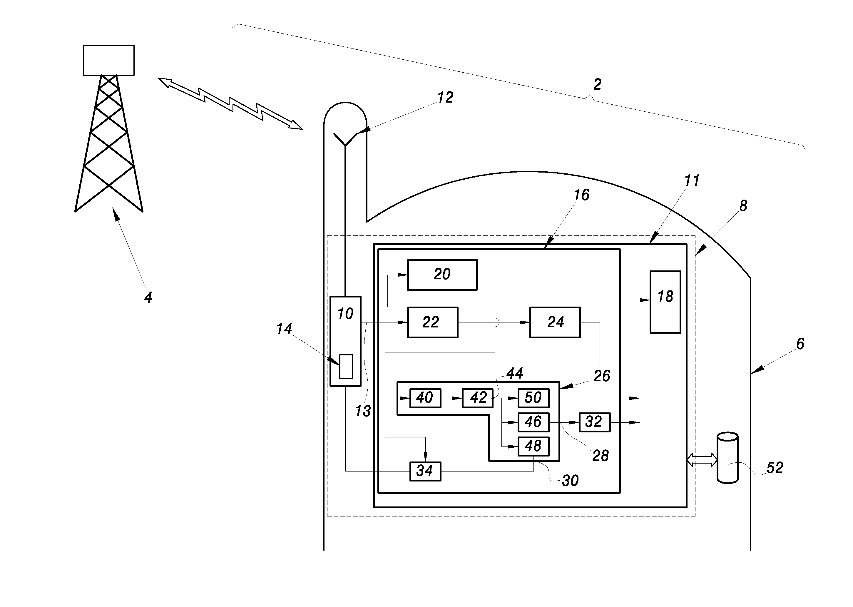
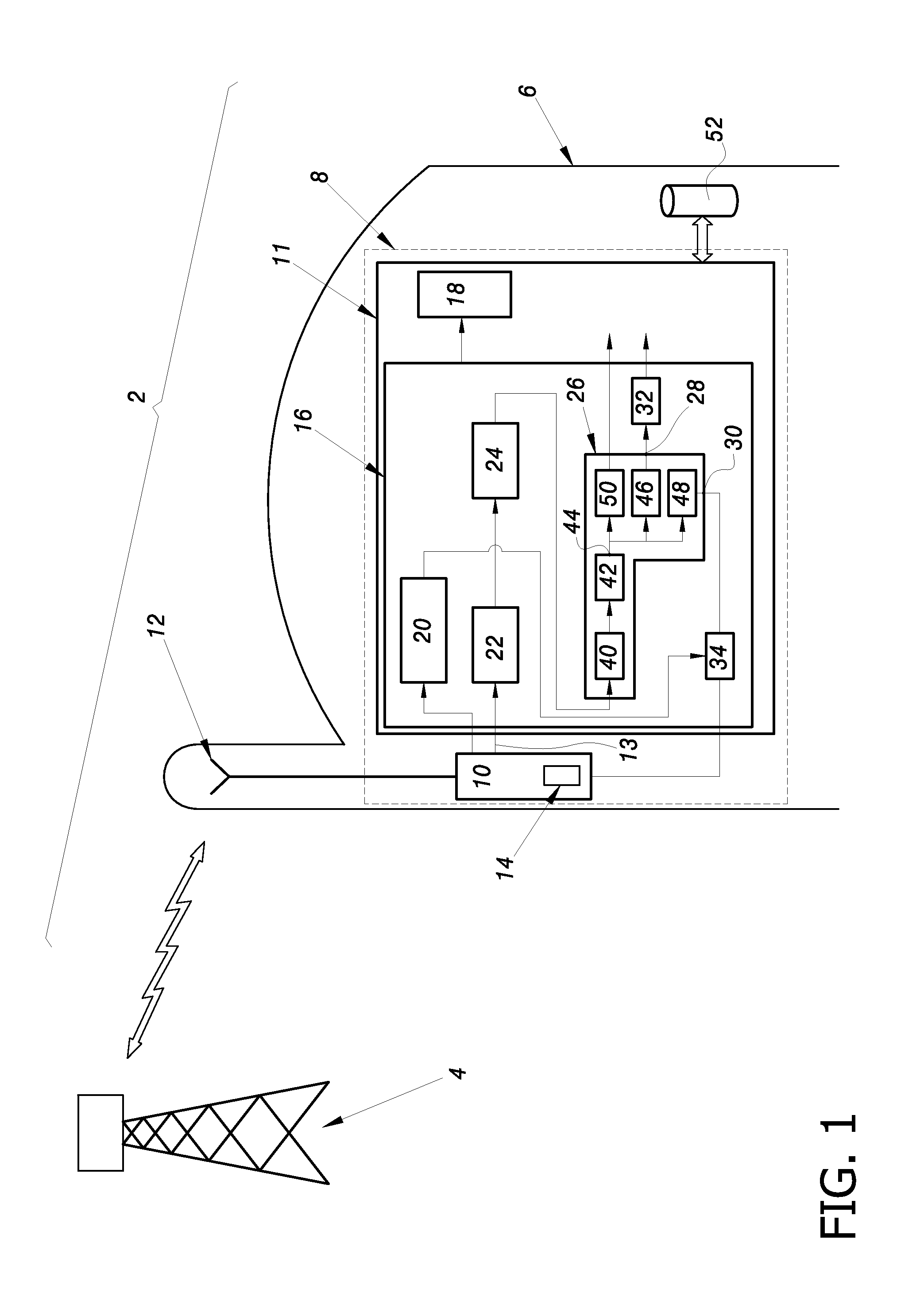
[0063]FIG. 1 shows parts of a UMTS radio communication system. System 2 comprises at least one node B like a base station 4 and one piece of wireless telecommunication user equipment 6 like a mobile phone. In the following description, functions or constructions well-known to a person of ordinary skill in the art are not described in detail.

[0064]Both node B and user equipment 6 include a wireless transmitter and a wireless receiver. For simplicity, only a wireless receiver 8 of user equipment 6 is shown in FIG. 1.

[0065]Receiver 8 has a radio frequency demodulation module 10 and a baseband processor 11.

[0066]Module 10 receives through an antenna 12 the radio signal transmitted by base station 4. Module 10 also demodulates the received radio signal and separates the different multiplexed channels. A plurality of channel signals is obtained. Each channel signal is transmitted from module 10 to processor 11 as a baseband signal. In UMTS radio communication systems, one of the physical ...


PUM


Abstract

Abstract: A method of estimating a Doppler maximum frequency fd and / or a local oscillator frequency offset f0, the method comprising the steps of: computing a power density spectrum of a received radio signal over a whole frequency range, scanning the computed power density spectrum to determine a frequency sub-range [fmin; fmax] which is not necessarily centered on 0 Hz, the signal power over the sub-range [fmin; fmax] being equal to a predetermined percentage of the signal power over the whole frequency range, and estimating frequency fd and / or offset f0 from frequencies fmin and fmax.

Description

FIELD OF THE INVENTION [0001]The present invention relates to a method, a program and a module to estimate a Doppler maximum frequency and / or an oscillator frequency offset, and a receiver including the module.BACKGROUND OF THE INVENTION[0002]In a radio communication system, the information bits are modulated at a transmitter end and consequently need to be demodulated at a receiver end. Thus, a radio receiver always has a RF (Radio Frequency) demodulation module. Basically, the RF demodulation module function consists of removing the carrier frequency from a received radio signal in order to recover a baseband signal. To perform this operation, a local oscillator part of the RF demodulation module, generates a frequency tone that ideally should be identical to the carrier frequency. The local oscillator should oscillate at the same frequency as the carrier frequency. Unfortunately, for several reasons (for instance the temperature variations) this local oscillator can drift. As a c...

Claims


Application Information

Patent Timeline
IPC IPC(8): G01S1/02G01S13/58
CPCH04B7/01H04L27/0014H04L2027/0016H04B17/309H04L2027/0046H04L2027/0065H04L2027/003
Inventor DEMAJ, PIERRE
Owner ST ERICSSON SA
Learn More