
Steam injection apparatus for steam assisted gravity drainage techniques

Inactive Publication Date: 2008-10-16
SCHLUMBERGER TECH CORP
View PDF19 Cites 73 Cited by
  • Summary
  • Abstract
  • Description
  • Claims
  • Application Information

AI Technical Summary

Benefits of technology

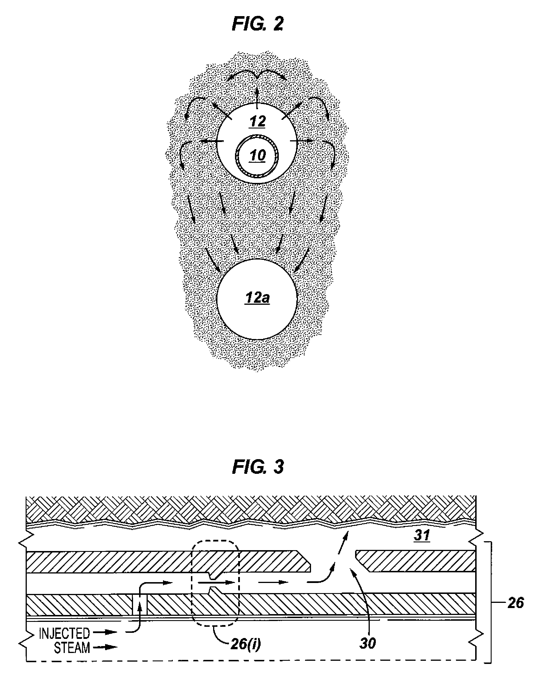
[0013]Additionally, steam injection pipe string apparatus according to the present invention may be implemented using sand-screen sections where the nozzle is arranged to direct the injected steam choked flow parallel to the wellbore. By using such sand screen apparatus, the flow of steam dissipates somewhat upon exiting the steam injection pipe string so as not to erode the wellbore. In another words, the use of a sand-screen apparatus to inject the steam into the steam injection wellbore lessens erosion of that wellbore.

Problems solved by technology

According to the '549 patent: (a) the economics of such projects is significantly impacted by the cost associated with generating steam; (b) SAGD does not typically employ the use of super-saturated steam because of the high cost of producing this steam with conventional hydrocarbon-fired tube boilers which results in using steam that is less efficient in transferring heat to the heavy oil reservoir; and (c) the produced water associated hydrocarbon production from these operations is typically disposed of in a commercially operated disposal well for a fee.
It is believed that the economics of SAGD may have been adversely impacted by the mechanisms heretofore utilized to inject steam and that the economics may be substantially increased by providing a homogeneous distribution of steam in the steam injection wellbore.

Method used


Image

  • Steam injection apparatus for steam assisted gravity drainage techniques
  • Steam injection apparatus for steam assisted gravity drainage techniques
  • Steam injection apparatus for steam assisted gravity drainage techniques

Examples


Embodiment Construction

[0024]It will be appreciated that the present invention may take many forms and embodiments. In the following description, some embodiments of the invention are described and numerous details are set forth to provide an understanding of the present invention. Those skilled in the art will appreciate, however, that the present invention practiced without those details and that numerous variations from and modifications of the described embodiments may be possible. The following description is thus intended to illustrate and not limit the present invention.

[0025]With reference first to FIG. 1, there is illustrated a system comprising a source of steam 20 located at the earth's surface. The source of steam 20 is coupled to one end of steam injection pipe string apparatus 10 in accordance with the present invention. Steam injection pipe string apparatus 10, as illustrated, is an elongated tubular structure and is located in steam injection wellbore 12. In SAGD operations, steam injectio...


PUM


Abstract

Steam injection pipe string apparatus is disclosed comprising an elongated tubular structure with first and second ends, and a plurality of orifices formed in the elongated tubular structure. The sizes of the orifices vary from one end of the elongated tubular structure to the other, and, in one embodiment, the sizes of the orifices increase from one end of the elongated tubular structure to the other. The elongated tubular structure may comprise a plurality of blank pipes in threaded engagement with one another or a plurality of subs with different sized orifices in the subs. The orifices may be formed in the elongated tubular structure using milling techniques or by inserting a nozzle in a threaded aperture formed in the structure. A system utilizing the steam injection pipe string apparatus is especially suitable for use in a steam assisted gravity drainage system.

Description

CROSS-REFERENCE TO RELATED APPLICATION[0001]This application claims the benefit of U.S. Provisional Patent Application No. 60 / 911,156, filed Apr. 11, 2007.BACKGROUND[0002]1. Field of the Invention[0003]This invention relates generally to oil recovery methods using steam assisted gravity drainage (SAGD) technology.[0004]2. Description of the Prior Art[0005]In many areas of the world, large deposits of viscous petroleum exist, and these deposits are often referred to as “tar sand” or heavy oil” deposits due to the high viscosity of the hydrocarbons which they contain. These tar sands may extend for many miles and occur in varying thicknesses of up to more then 300 feet. Although tar sand deposits may lie at or near the earth's surface, generally they are located under a substantial overburden which may be as great as several thousand feet thick. Tar sands located at these depths constitute some of the world's largest presently known petroleum deposits. The tar sands contain a viscous ...

Claims


Application Information

Patent Timeline
IPC IPC(8): E21B43/16B05B1/14
CPCE21B43/2406
Inventor FORBES, KEVIN J.OVUTMEN, NIHAT
Owner SCHLUMBERGER TECH CORP
Learn More