Valve element opening/closing device

a valve element and opening/closing technology, which is applied in the field of valve element opening/closing devices, can solve the problems of increasing the size and manufacturing cost and the size of the valve element opening/closing device and its manufacturing cost, and achieves the effect of simple structur

Inactive Publication Date: 2008-10-16
SANKYO SEIKI MFG CO LTD
View PDF9 Cites 6 Cited by
  • Summary
  • Abstract
  • Description
  • Claims
  • Application Information

AI Technical Summary

Benefits of technology

[0007]In view of the problems described above, an embodiment of the present invention may advantageously provide a valve element opening / closing device in which a flow passage for fluid can be securely closed with a simple structure even when the number of input ports in the valve element opening / closing device is increased and a total sum of fluid pressures applied to the device becomes larger.
[0010]According to the valve element opening / closing device in accordance with the embodiment of the present invention, the valve element which opens and closes a flow passage for fluid is disposed on an outer side of the main body, i.e., on the inflow pipe side with respect to the opening through which the fluid flows, in the valve element opening / closing device. Therefore, the valve element is urged in the closing direction by the fluid pressure of the inputted fluid. Accordingly, when the opening is to be in the closed state, a force against the fluid pressure is not required and thus the flow passage can be securely closed. Further, the valve element is operated in the axial direction to attain the open state or the close state of the opening and thus the valve element can be accommodated within the inflow pipe connected to the opening and the size of the valve element opening / closing device can be reduced.
[0013]In accordance with an embodiment of the present invention, the valve element opening / closing device is provided with a mode in which all of the flow passages are set to be in an open state by using each of the plurality of the valve elements. As described above, when the valve element opening / closing device is provided with a mode in which all of the flow passages are set to be in an open state, all the valve elements can be set at positions separated from the respective openings. Therefore, when the valve element opening / closing device is assembled into a refrigerator or the like, the valve elements can be prevented from being damaged by welding heat by means of that all the valve elements are set to be separated from the openings.
[0015]According to the structure as described above, the valve element is always urged in a direction where the opening is closed by the urging member. Therefore, only when the valve element is to be moved in the direction where the opening is opened, a drive force of the motor that is a drive source is used through the linearly moving mechanism part. Accordingly, electric power consumption in the valve element opening / closing device can be restrained.
[0017]In accordance with an embodiment of the present invention, the valve element opening / closing device includes a turning prevention mechanism which is provided in the linearly moving mechanism part for restricting turning of the valve element, a rotary power transmission member for transmitting a drive force of the motor to the linearly moving member, and a shaft by which the rotary power transmission member is turnably supported. The turning prevention mechanism includes a protruded part which is provided in the linearly moving member, and a recessed part which is formed in the shaft and engaged with the protruded part which is provided in the linearly moving member. As described above, the turning prevention mechanism is provided between the linearly moving member of the linearly moving mechanism part and the shaft on which the rotary power transmission member for transmitting a drive force of the motor to the linearly moving member is turnably supported. Therefore, other separate member as the turning prevention member for the valve element is not required and thus the structure of the valve element opening / closing device can be made compact.
[0019]In accordance with an embodiment of the present invention, a turning restriction part is provided in the rotary power transmission member for restricting a turning amount of the rotary power transmission member to less than one rotation. As described above, when the turning restriction part is provided in the rotary power transmission member for restricting its turning amount to less than one rotation, a new separate member is not required as a turning restriction member for the rotary power transmission member such as a gear and thus the structure of the valve element opening / closing device can be made compact. Specifically, the turning restriction part may be provided in the transmitting gear for restricting its turning amount to less than one rotation.

Problems solved by technology

As a result, a size and a manufacturing cost of the valve element opening / closing device are increased.
Therefore, a force for closing the flow passage for fluid is required to farther increase and thus the size of the valve element opening / closing device and its manufacturing cost are further increased.

Method used


Image

  • Valve element opening/closing device
  • Valve element opening/closing device
  • Valve element opening/closing device

Examples


first embodiment

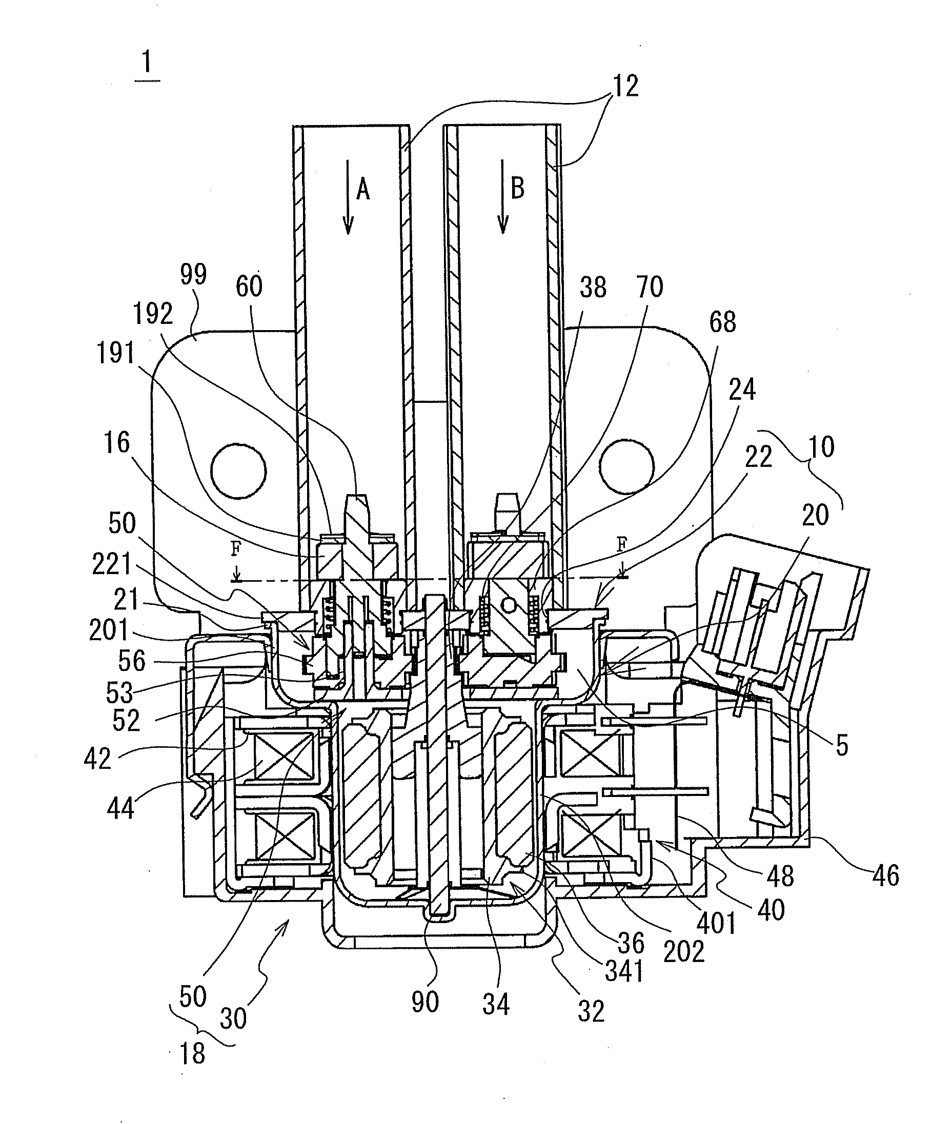
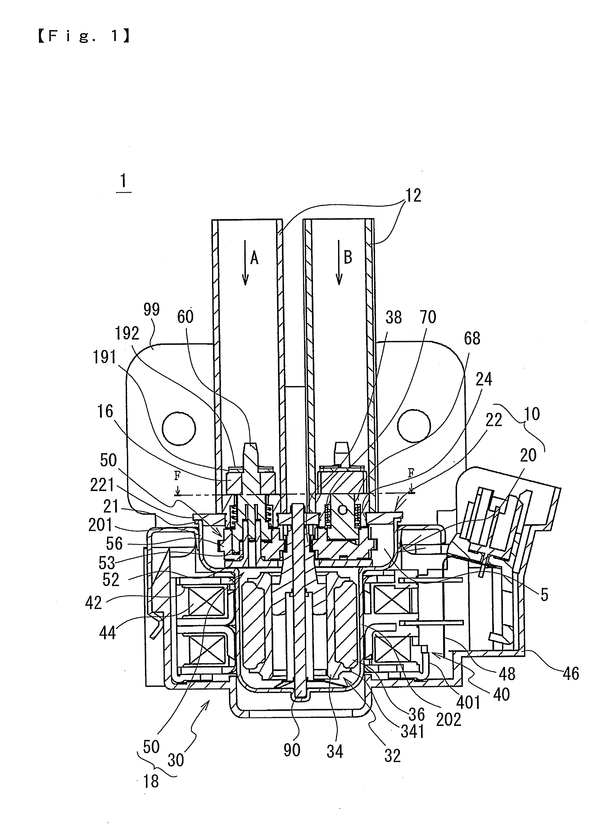
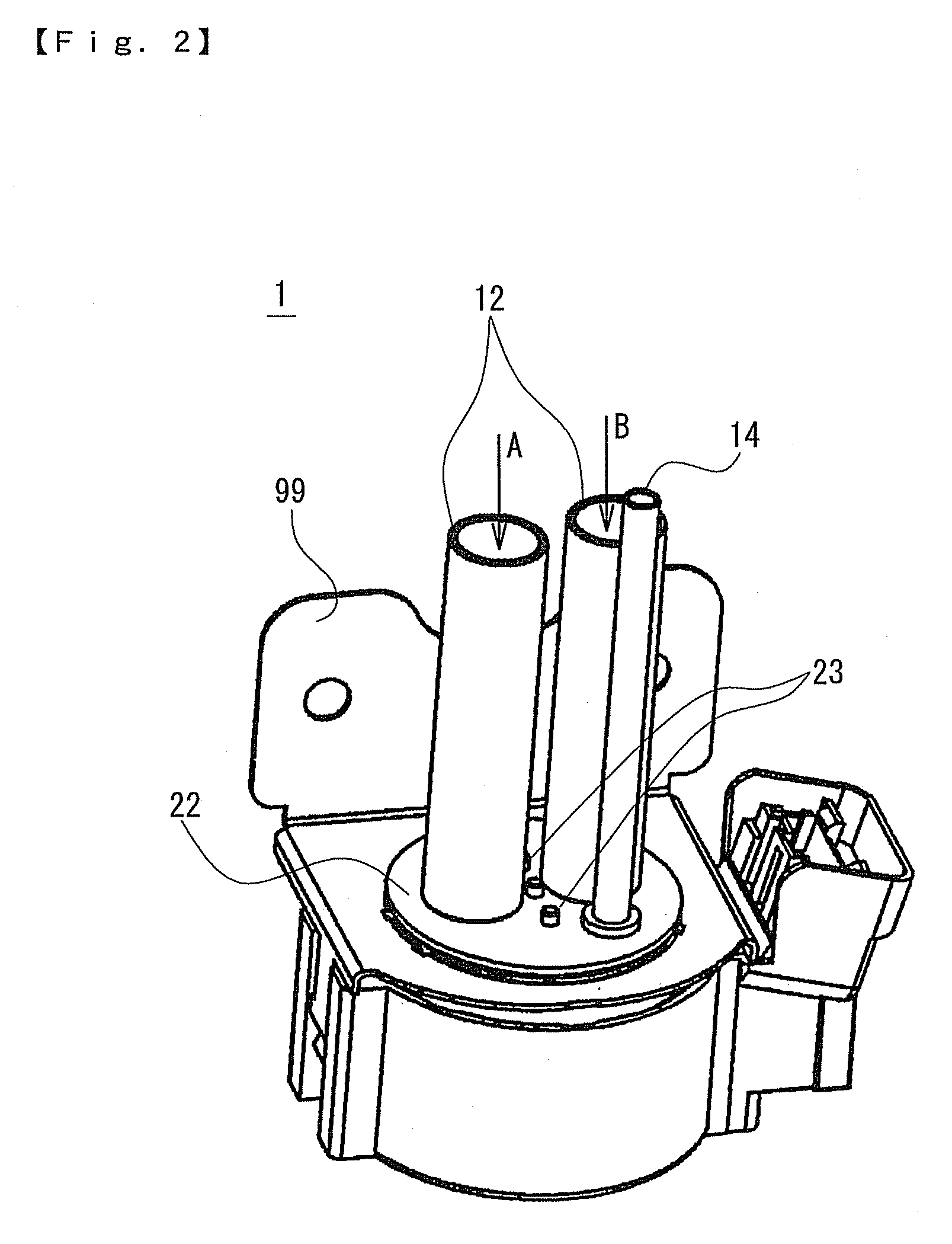
[0032]An embodiment of the present invention will be described in detail below with reference to the accompanying drawings. FIG. 1 is a cross-sectional view showing a valve element opening / closing device 1 in accordance with the present invention and FIG. 2 is its perspective outward appearance view.

[0033]The valve element opening / closing device 1 is a so-called “2-IN / 1-OUT” valve which is capable of selectively outputting, e.g. passing either one of two kinds of fluids, e.g., two kinds of fluids whose temperatures are different from each other, which are inputted or flown into the device. In this embodiment, structural components for controlling fluid “A” inputted into the device have the same structure as those for controlling fluid “B”. Therefore, when it is required to be distinguished from each other, the notational symbol “a” is added to the structural components for controlling the fluid “A” and the notational symbol “b” is added to the structural components for controlling t...

second embodiment

[0075]As described above, the valve element opening / closing device in accordance with the second embodiment provides eight modes as open / close states of the valve elements 16a through 16c. In these modes, when the modes where either one of the valve elements 16a through 16c is set to be in the open state are appropriately changed, in other words, when the mode (2. open-close-close), the mode (4. close-open-close) and the mode (6. close-close-open) are appropriately changed, either one of three fluids to be inputted is selectively passed.

[0076]According to this valve element opening / closing device, in three kinds of fluid to be inputted into the valve element opening / closing device, when the modes where two or more kinds of fluid are mixed and passed are appropriately changed, in other words, when the mode (3. open-open-close), the mode (5. close-open-open), the mode (7. open-close-open), and the mode (8. open-open-open) are appropriately changed, a temperature of fluid to be outputt...


PUM


Abstract

A valve element opening / closing device may include a main body formed with a space, an inflow pipe and an outflow pipe which are connected to the main body, a valve element for opening and closing a flow passage, and a drive part for driving the valve element to open and close the flow passage. The valve element may be arranged on an inflow pipe side with respect an opening of the main body to which the inflow pipe is connected. The valve element is preferably arranged within the inflow pipe.

Description

CROSS REFERENCE TO RELATED APPLICATION[0001]The present invention claims priority under 35 U.S.C. §119 to Japanese Application No. 2007-104621 filed Apr. 12, 2007, which is incorporated herein by reference.FIELD OF THE INVENTION[0002]An embodiment of the present invention may relate to a valve element opening / closing device. More specifically, an embodiment of the present invention may relate to a valve element opening / closing device in which a valve element is operated by a motor to open and close a flow passage.BACKGROUND OF THE INVENTION[0003]Valve element opening / closing devices have been conventionally known in which a valve element is driven by a motor as a drive source to open and close a flow passage for refrigerant in a refrigerator or the like. In Japanese Patent Laid-Open No. 2002-349740, a valve element opening / closing device is disclosed in which a valve element is mounted on a screw member and the valve element is advanced or retreated in its axial direction by means o...

Claims


Application Information

Patent Timeline
Patent Type & Authority Applications(United States)
IPC IPC(8): F16K11/22F16K1/00F16K31/44
CPCF16K11/165F16K31/04Y10T137/87096Y10T137/87692
Inventor HARA, TETSUHIKO
Owner SANKYO SEIKI MFG CO LTD
Why Eureka
Try Eureka