
Data transfer scheme using caching and differential compression techniques for reducing network load

a data transfer and differential compression technology, applied in the field of data transfer schemes, can solve the problems of increasing the amount of data that cannot be handled by the conventional caching technique, the ineffective use of the caching technique alone, and the inability to reduce the network load. the effect of reducing the network load of the network

Inactive Publication Date: 2008-10-09
KK TOSHIBA
View PDF23 Cites 9 Cited by
  • Summary
  • Abstract
  • Description
  • Claims
  • Application Information

AI Technical Summary

Benefits of technology

This approach effectively reduces network load by efficiently managing and compressing data transfers, especially for private and dynamic data, and data handled through POST and PUT methods, improving network performance in Web-based systems.

Problems solved by technology

Consequently, a capacity (bandwidth) of the network to be used for communications between the client and the server tends to be a bottleneck of the entire system.
However, the latter private data are not cachable for a shared cache such as that of the proxy server (because there is a need for the server to return the private data after carrying out the user authentication).
However, in conjunction with the spread of a system in which the user makes accesses to the information or services on the server via the network by using the Web browser such as that of Web based ASP (Application Service Provider), the amount of data that cannot be handled by the conventional caching technique is increasing.
As a consequence, the use of the caching technique alone has been becoming rather ineffective as a method for reducing the network load.

Method used


Image

  • Data transfer scheme using caching and differential compression techniques for reducing network load
  • Data transfer scheme using caching and differential compression techniques for reducing network load
  • Data transfer scheme using caching and differential compression techniques for reducing network load

Examples


Embodiment Construction

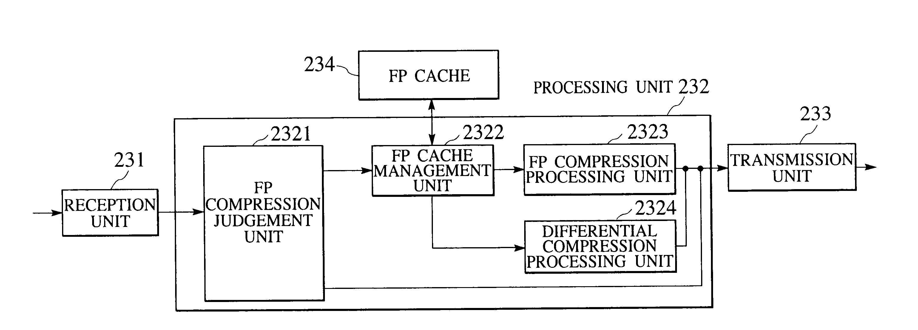
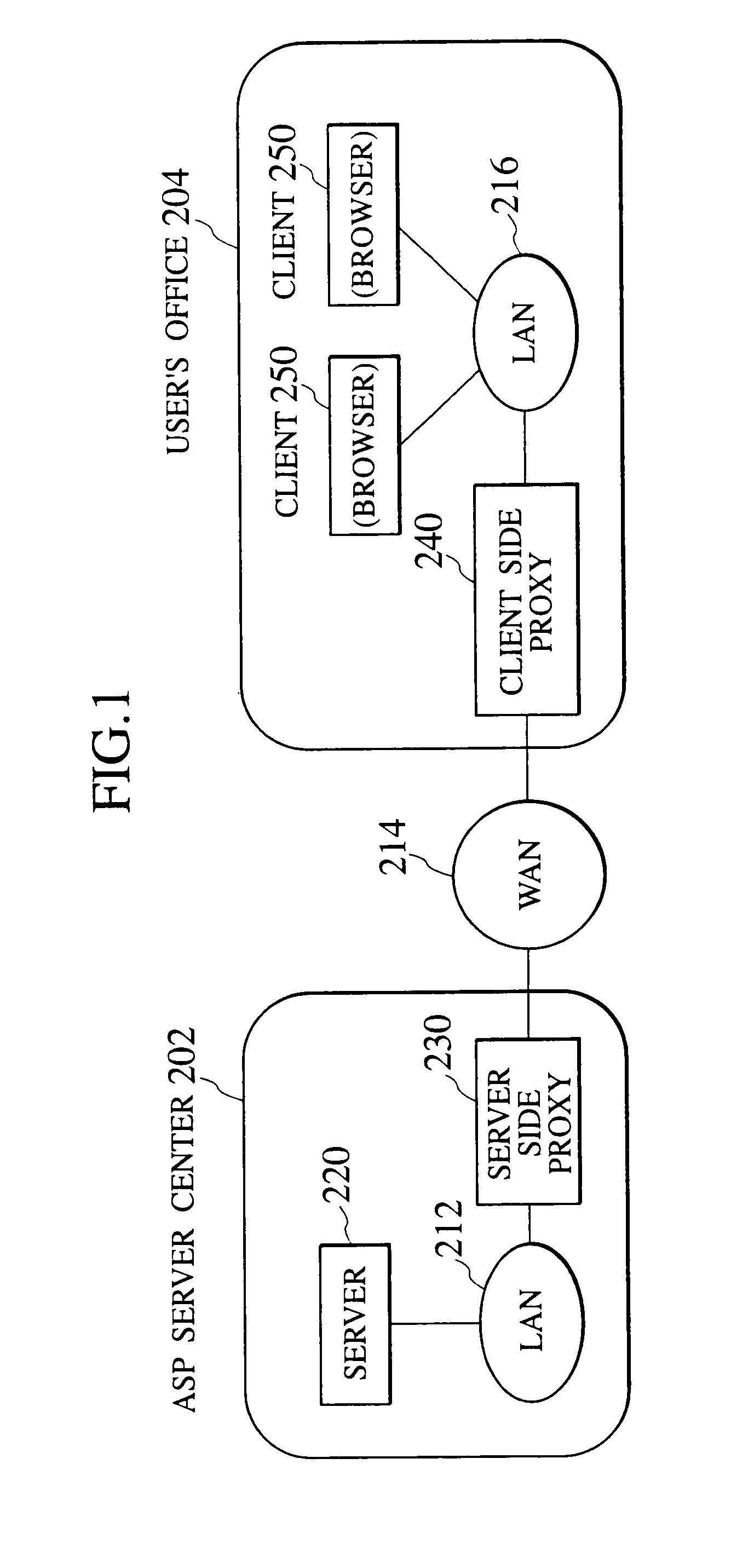
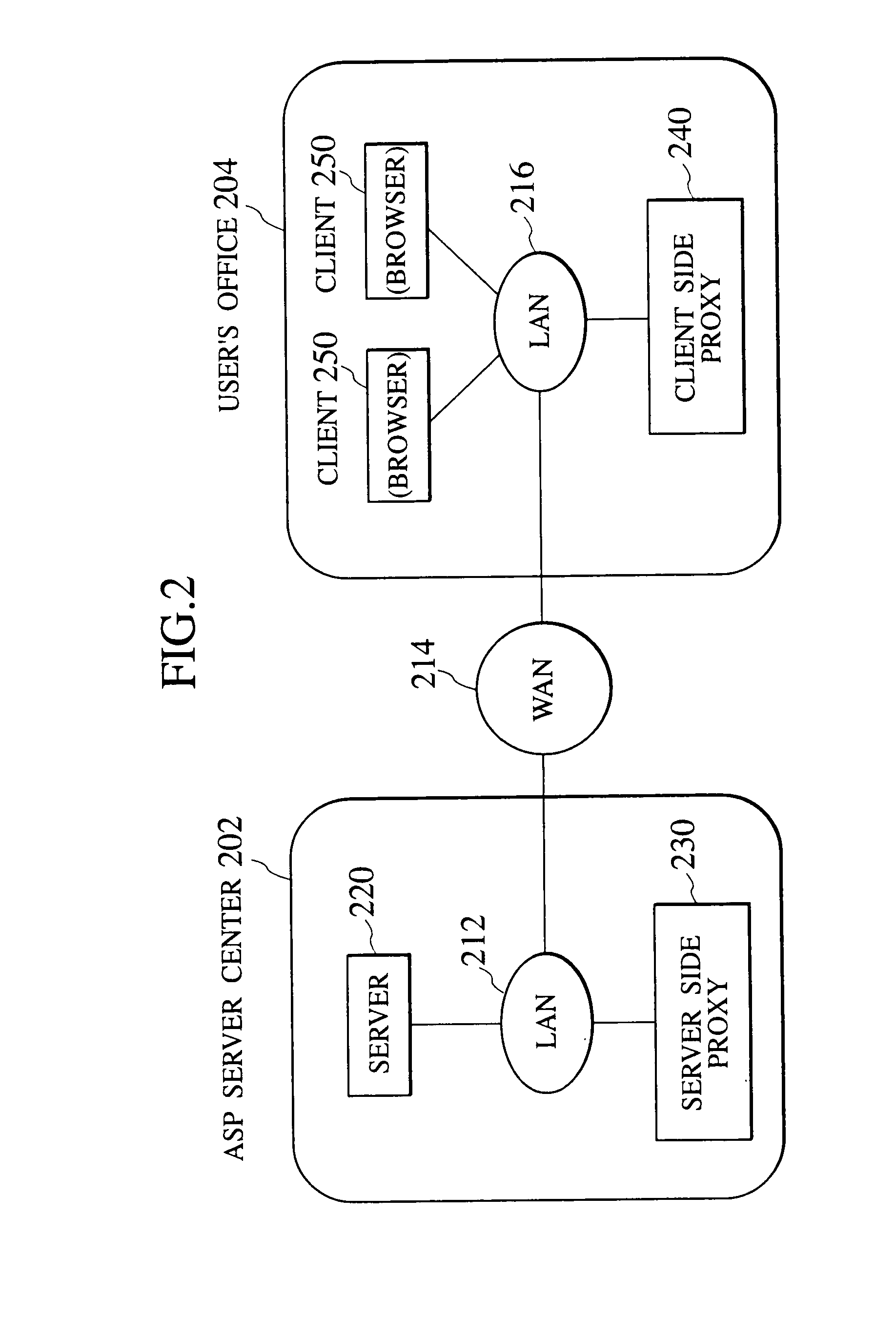
[0084]Referring now to FIG. 1 to FIG. 52, one embodiment of the data transfer scheme according to the present invention will be described in detail.

[0085]In the following, an exemplary case in which a WAN is the Internet, clients are connected to a user's office LAN, and the HTTP protocol is used will be described, but the present invention is also applicable to the cases where the WAN is other than the Internet, the cases where the clients are located at LAN other than the user's office LAN such as a LAN inside a home, and the cases where the protocol other than the HTTP protocol is to be used.

[0086]FIG. 38 shows an exemplary basic configuration of a computer network system to which the present invention is applied. In this exemplary configuration, a local area network (LAN) 212 inside an ASP server center 202 and a local area network (LAN) 216 inside a user's office 204 are connected through a wide area network (WAN) 214 such as the Internet or dedicated line, such that a server 2...


PUM


Abstract

In a data transfer scheme using a caching technique and / or a compression technique which is capable of reducing the network load of a network connecting between data transfer devices, correspondences between data and their names are registered at the data transfer devices and the corresponding names are transferred, instead of transferring the data, for those data for which the correspondences are registered, so that it is possible to reduce the amount of transfer data among the data transfer devices. Even when the name corresponding to the data is not registered so that it is impossible to transfer the corresponding name instead of transferring the data, it is possible to reduce the amount of transfer data among the data transfer devices by transferring the compressed data in which this data is expressed in a compressed form by utilizing the name corresponding to the registered reference data.

Description

BACKGROUND OF THE INVENTION[0001]1. Field of the Invention[0002]The present invention relates to a data transfer scheme for carrying out data transfer at a data transfer device on behalf of another device.[0003]2. Description of the Related Art[0004]The client-server type information system formed by servers for providing various services through a network and clients for requesting desired services to the servers has been widely used. In particular, the World Wide Web system (which is also simply called Web) formed by Web servers and clients that communicate with each other by using the HTTP protocol on the Internet is the very widely used client-server type information system. Usually, a server program is operating on a server and a prescribed tool (program) such as a browser is operating on a client. The contents of the services provided on the Internet are also wide ranging so that there are various existing services including services for providing, delivering or transferring i...

Claims


Application Information

Patent Timeline
Patent Type & Authority Applications(United States)
IPC IPC(8): G06F15/16G06F5/00G06F12/00H04L29/06H04L29/08
CPCH04L29/06H04L69/04H04L67/2852H04L67/2876H04L67/5682H04L9/40
Inventor KANAI, TATSUNORISEKI, TOSHIBUMIYOSHII, KENICHIROSATO, HIDEAKIMIYAZAWA, TAKAYUKITOYAMA, HARUHIKOKIMURA, YASUHIROYOSHIDA, HIDEKI
Owner KK TOSHIBA
Learn More