Prosthetic valve that permits retrograde flow
a technology of retrograde flow and prosthesis, applied in the field of medical devices, can solve the problems of loss of effectiveness, physical manifestations and pathologies, and insufficient venous valves, and achieve the effects of preventing pooling of blood, preventing the formation of thrombosis, and increasing the overall acceptance of the device by the hos
- Summary
- Abstract
- Description
- Claims
- Application Information
AI Technical Summary
Benefits of technology
Problems solved by technology
Method used
Image
Examples
first embodiment
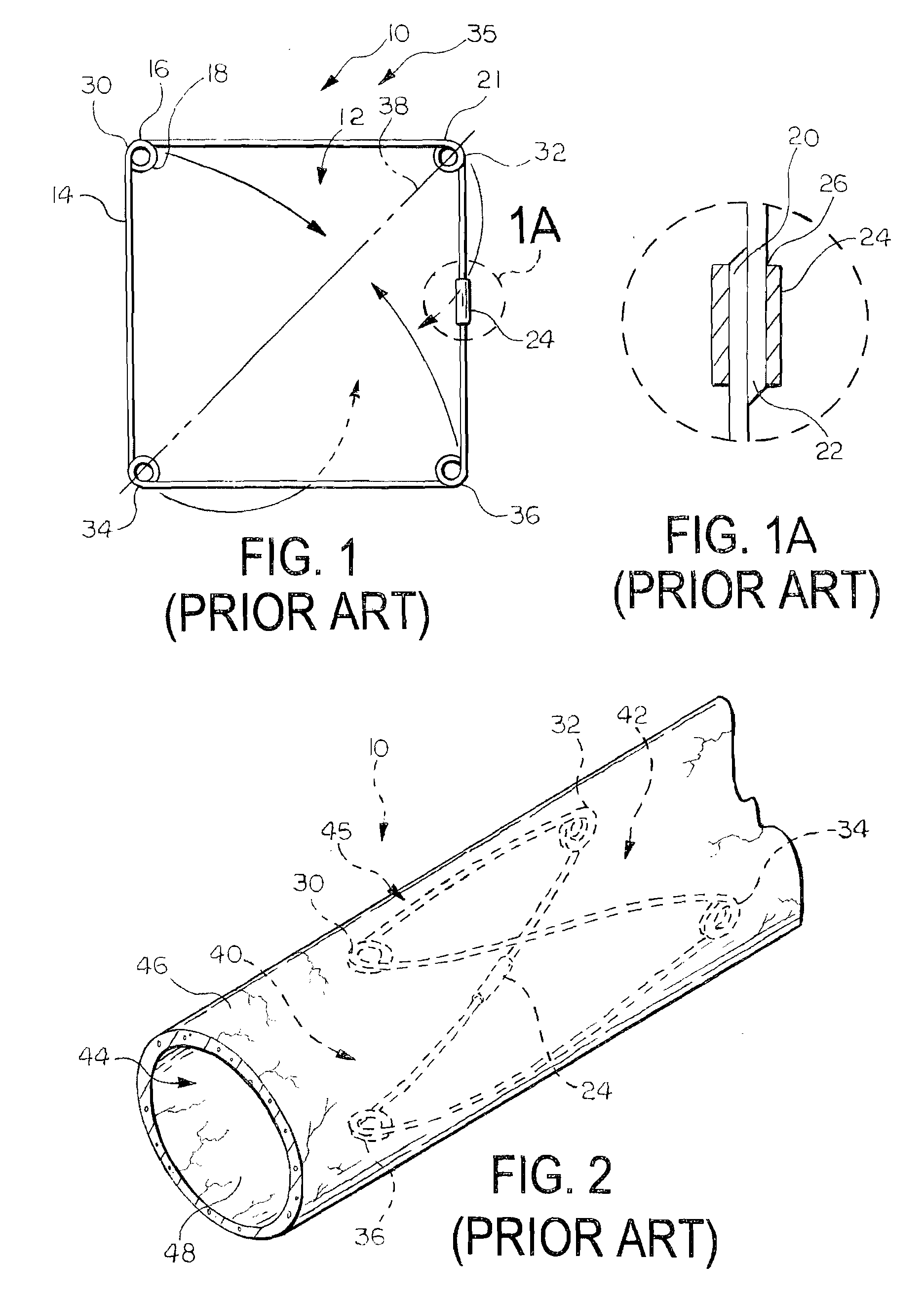
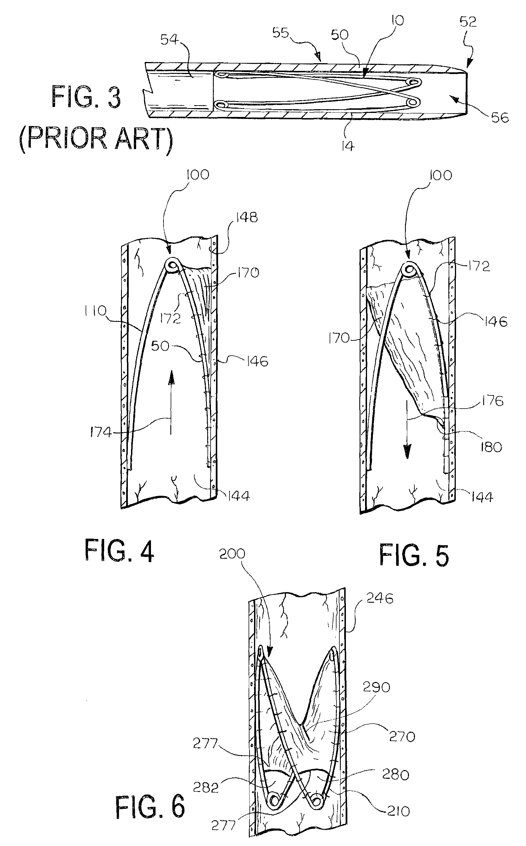
[0060]FIGS. 4 and 5 illustrate a medical device 100 according to the invention. The device 100 includes a support frame 110 and a valve leaflet 170 attached to the support frame 110. In this embodiment, the support frame 110 is the support frame 10 illustrated in FIGS. 1, 1A, 2, and 3.
[0061]The valve leaflet 170 comprises a section of material, such as a sheet, that is attached to the support frame 110. The valve leaflet 170 can be formed of any suitable material, and need only be biocompatible or be able to be made biocompatible. The material can advantageously be formed of a flexible material. Examples of suitable materials for the valve leaflet 170 include natural materials, synthetic materials, and combinations of natural and synthetic materials. Examples of suitable natural materials include extracellular matrix (ECM) materials, such as small intestine submucosa (SIS), and other bioremodellable materials, such as bovine pericardium. Other examples of ECM materials that can be u...
second embodiment
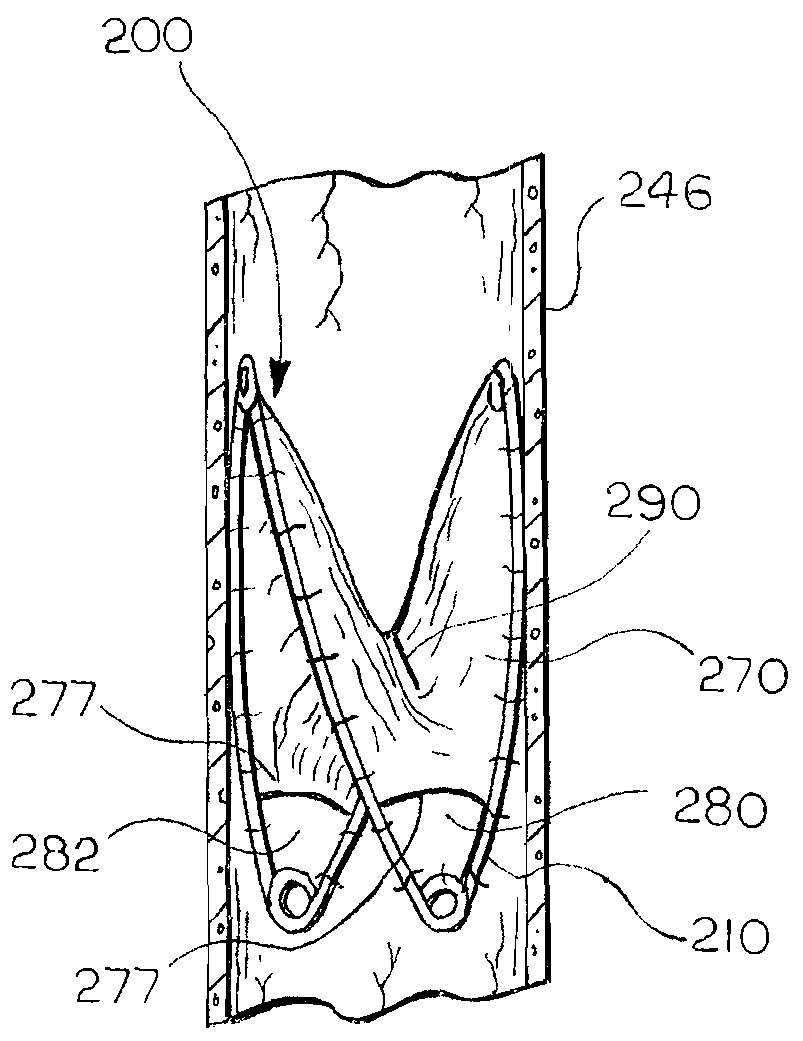
[0069]FIG. 6 illustrates a medical device 200 according to the invention. In this embodiment, the leaflet 270 spans the entire support frame 210, and includes a slit 290 that defines an aperture in the leaflet 270. The leaflet 270 opens and closes the slit 290 to permit flow in a first direction and substantially prevent flow in a second, opposite direction, i.e., retrograde flow, by moving the slit from a first open position to a second closed position. The slit 290 can be oriented relative to the frame 210 as shown, or in any other suitable orientation.
[0070]In this embodiment, the medical device 200 includes multiple openings 280, 282 for allowing a controlled amount of retrograde flow to pass through the device 200 when the slit 290 is in the second, closed position. Each of the openings 280, 282 is as described above for the first embodiment and the total cumulative open area of the openings 280, 282 is, at a maximum, less than the cross-sectional area of the vessel 246 at the ...
third embodiment
[0071]FIG. 7 illustrates a medical device 300 according to the invention. In this embodiment, the device 300 includes two leaflets 346, 348 that are attached to the support frame 310. Each leaflet 346, 348 has a free edge 350, 352 that is not attached to the support frame 310. The free edges 350, 352 cooperatively define valve orifice 392. The leaflets 346, 348 are both movable between first and second positions. In the first position, illustrated in FIG. 7, the orifice 392 is open and allows fluid flow through the device 300 in a first direction, represented by arrow 374. In the second position, the free edges 350, 352 of leaflets 346, 348 come together to close the orifice 392 and substantially prevent fluid flow through the device in a second, opposite direction.
[0072]Each leaflet 346, 348 defines an opening 380, 382 that allows a controlled amount of retrograde flow to pass through the medical device 300 when the valve orifice 392 is closed. In this embodiment, each of the openi...
PUM
 Abstract
Description
Claims
Application Information
 - R&D
- Intellectual Property
- Life Sciences
- Materials
- Tech Scout
- Unparalleled Data Quality
- Higher Quality Content
- 60% Fewer Hallucinations
Browse by: Latest US Patents, China's latest patents, Technical Efficacy Thesaurus, Application Domain, Technology Topic, Popular Technical Reports.
© 2025 PatSnap. All rights reserved.Legal|Privacy policy|Modern Slavery Act Transparency Statement|Sitemap|About US| Contact US: help@patsnap.com


