
Method for Automatically and Sequentially Loading Objects and Corresponding Equipment

a technology of automatic and sequential loading and corresponding equipment, applied in the field of methods, can solve the problems of deterioration of appearance, loss of quality of angular location, and cost of machine stoppage and replacement parts

Active Publication Date: 2008-10-09
SAVERGLASS
View PDF16 Cites 16 Cited by
  • Summary
  • Abstract
  • Description
  • Claims
  • Application Information

AI Technical Summary

Benefits of technology

[0039]Finally, another advantage of the invention lies in that it may be used irrespective of the shape of the object (square, oval, cylindrical, etc.).
lies in that it may be used irrespective of the shape of the object (square, oval, cylindrical, etc.).

Problems solved by technology

When a user desires to decorate a packaging object made of glass or organic material (flask, carafe, bottle or cosmetic pot for example), via a conventional method such as screen-printing or pad-printing, the user is faced with the problem of setting the decoration to be placed with on the one hand the geometric particular features of the object and, on the other hand, decorations or decoration roughs that may already exist, knowing that the objects have a random angular position.
When the skirt and the object are placed in relative rotation, the friction between the movable elements (skirt and pin) and the fixed elements (bottom of the object) leads on the one hand to a deterioration of the appearance of the bottom in the case of objects coated with a varnish, a lacquer, or a chemical satin finish; but its also leads to the wear of the skirt and / or the pin, which may occur after several hours of operation, which causes a loss of quality of angular location, and even a breakage of the object, which leads to a cost of machine stoppage and of replacement parts.
These elements may also lead to limiting the speed of rotation of the skirt and hence to reducing the overall rate of production.
Furthermore, this type of method leads to a limited precision, because of the mechanical tolerances of the object, of the pin and of the notch, these tolerances being able to lead, by accumulation, to nonconformities.

Method used


Image

  • Method for Automatically and Sequentially Loading Objects and Corresponding Equipment
  • Method for Automatically and Sequentially Loading Objects and Corresponding Equipment
  • Method for Automatically and Sequentially Loading Objects and Corresponding Equipment

Examples


Embodiment Construction

)

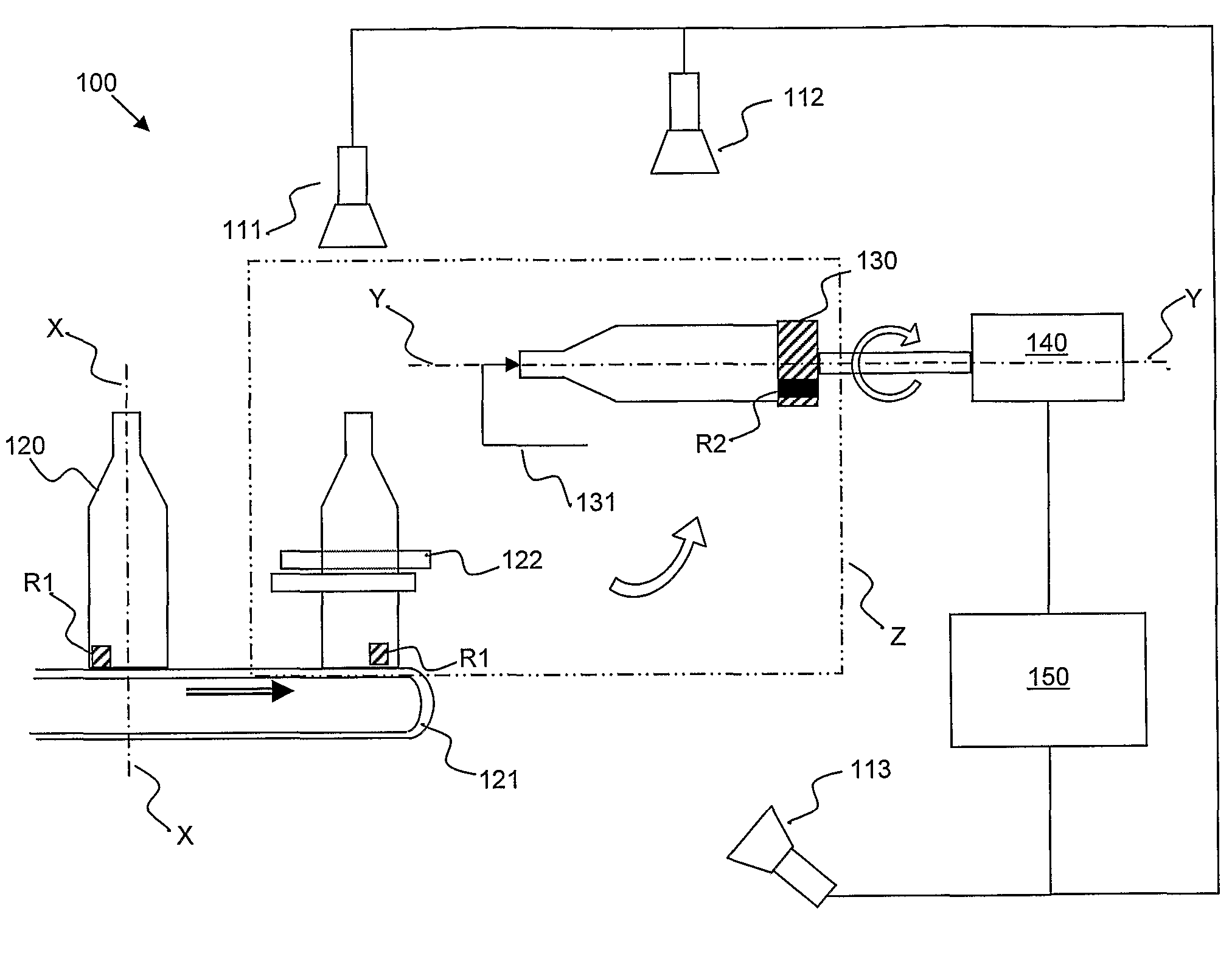
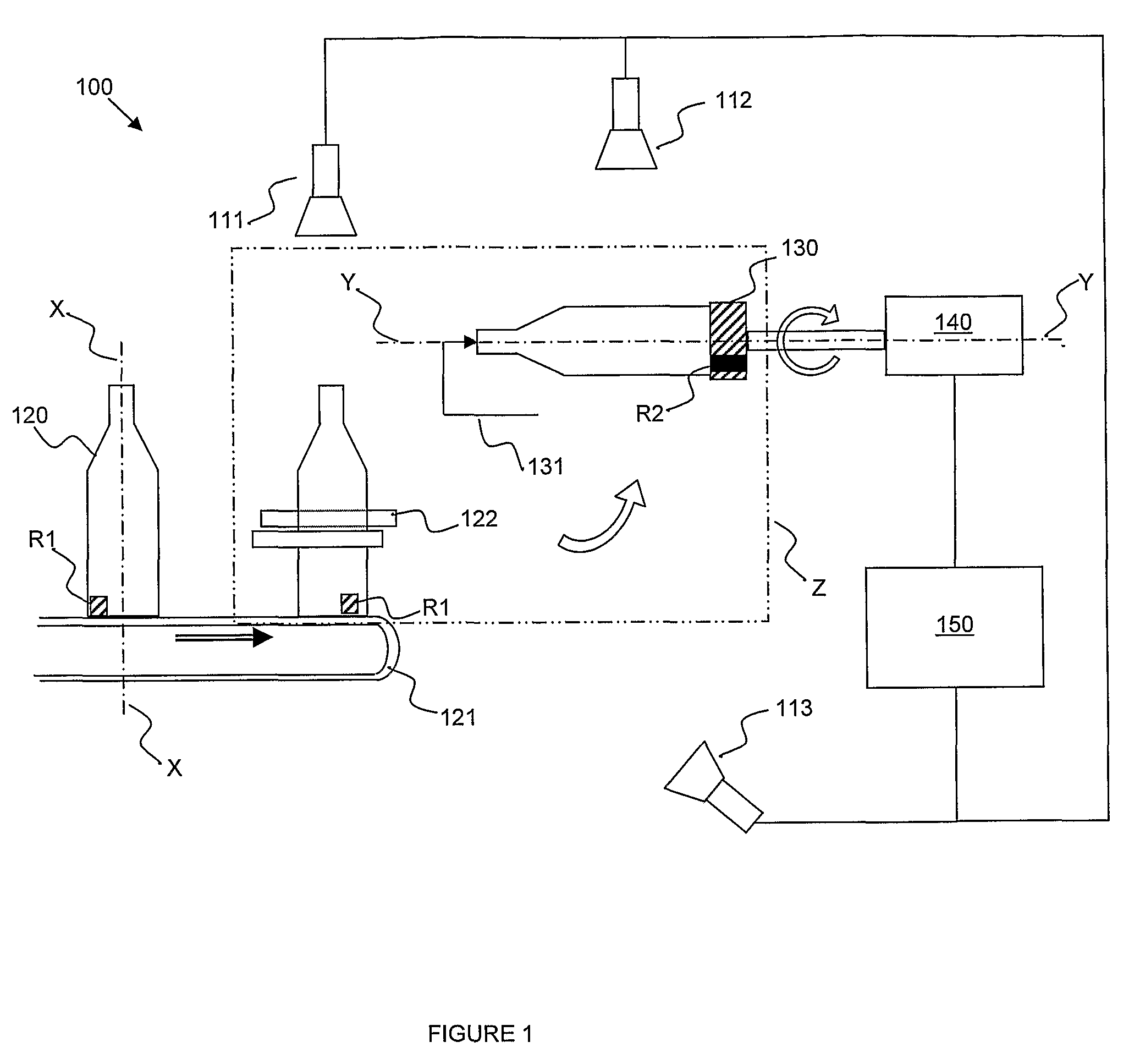
[0043]With reference to FIG. 1, the invention relates in particular to an item of equipment 100 for the automatic and sequential loading of objects 120 of a predetermined type onto a holding device 130. Preferably, the object is a bottle, a flask or a carafe. It may also be a cosmetic pot. Also preferably, it is a glassware article.

[0044]A particular example of such an item of equipment is a rotary or linear multicolor screen-printing machine for a glassware article.

[0045]In one embodiment, the holding device comprises at least one skirt 130 and advantageously a tailstock center 131 (partially shown).

[0046]Each object 120 and the holding device 130 has respective first XX and second YY axes of rotation and respective first R1 and second R2 locators of rotation about these respective axes.

[0047]As schematically represented in FIG. 1, the loading of each object 120 onto the holding device 130 leads to a contact of this object with this device, to an alignment of the first and second ...


PUM


Abstract

A method is provided for automatically and sequentially loading objects onto a feed system, each having a respective axis of rotation and respective first and second indices of rotation about the respective axes. The loading of each object onto the feed system causes an orientation in a predetermined relative position. The method consists in particular in selectively operating a relative rotation of the object and of the handling device about their axis of rotation to achieve the orientation.

Description

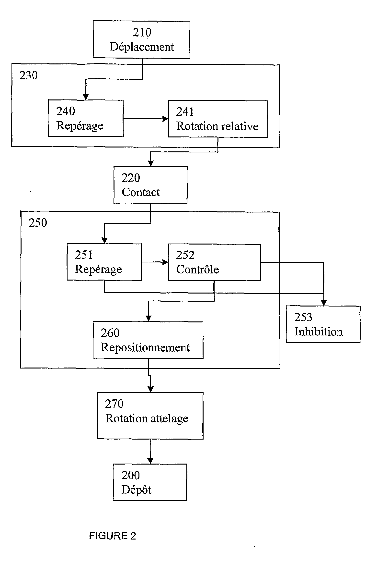
BACKGROUND[0001](1) Field of Invention[0002]The present invention relates, in general, to the field of methods, and associated equipment, for automatic and sequential loading of objects, particularly for the purpose of placing a decoration on each object.[0003]More precisely, the invention relates to a method for automatic and sequential loading of objects of a predetermined type onto a holding device, each object and the holding device having first and second respective axes of rotation and first and second respective locators of rotation about these respective axes, the loading of each object onto the holding device leading to a contact of this object with this device, to an alignment of the first and second axes, and to an angular setting of the first and second locators in a predetermined relative angular position, this method comprising the steps consisting in carrying out a movement of each object until it is in contact with the holding device and selectively carrying out a re...

Claims


Application Information

Patent Timeline
IPC IPC(8): B65G65/00
CPCB41F15/0872B41P2215/11B41P2217/60B41P2217/62B65C9/067B65G47/24B65G2201/0244
Inventor LOURMAN, DIDIERHECKMANN, DIDIER
Owner SAVERGLASS
Learn More