
Profile for sliding windows or doors, method for making the profile, and window or door obtained with the profile

a technology profiles, applied in the field of profiles for sliding windows or doors, can solve the problems of insufficient heat insulation relative to the other types of windows or doors, inability to achieve acceptable performance, and difficulty in using this type of window or door, so as to achieve high heat insulation properties and maintain mechanical and aesthetic similarity.

Active Publication Date: 2008-10-09
GSG INT
View PDF41 Cites 16 Cited by
  • Summary
  • Abstract
  • Description
  • Claims
  • Application Information

AI Technical Summary

Benefits of technology

[0020]Another aim of the present invention is the definition of a method for making the profile with extremely simple steps and reduced additional costs.
[0021]Another aim of the present invention is to obtain a sliding window or door with the above-mentioned profile, having high level heat insulation properties, combined with simplified transport and assembly of its basic elements.

Problems solved by technology

However, in contrast to these undoubted advantages of the sliding window or door there is an insufficient level of heat insulation relative to the other types of windows or doors (see for example windows and doors with tilt and turn opening).
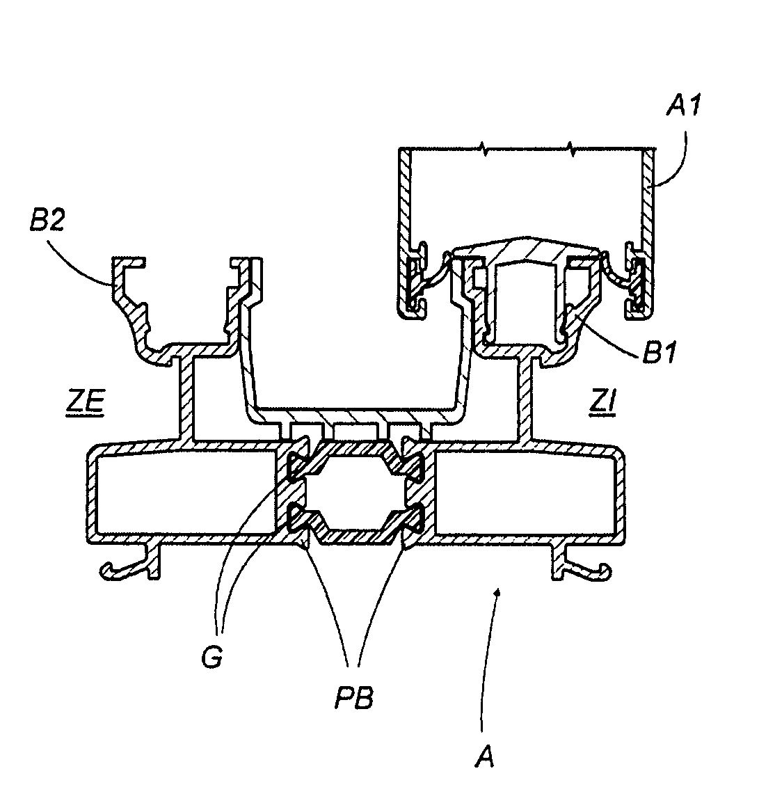
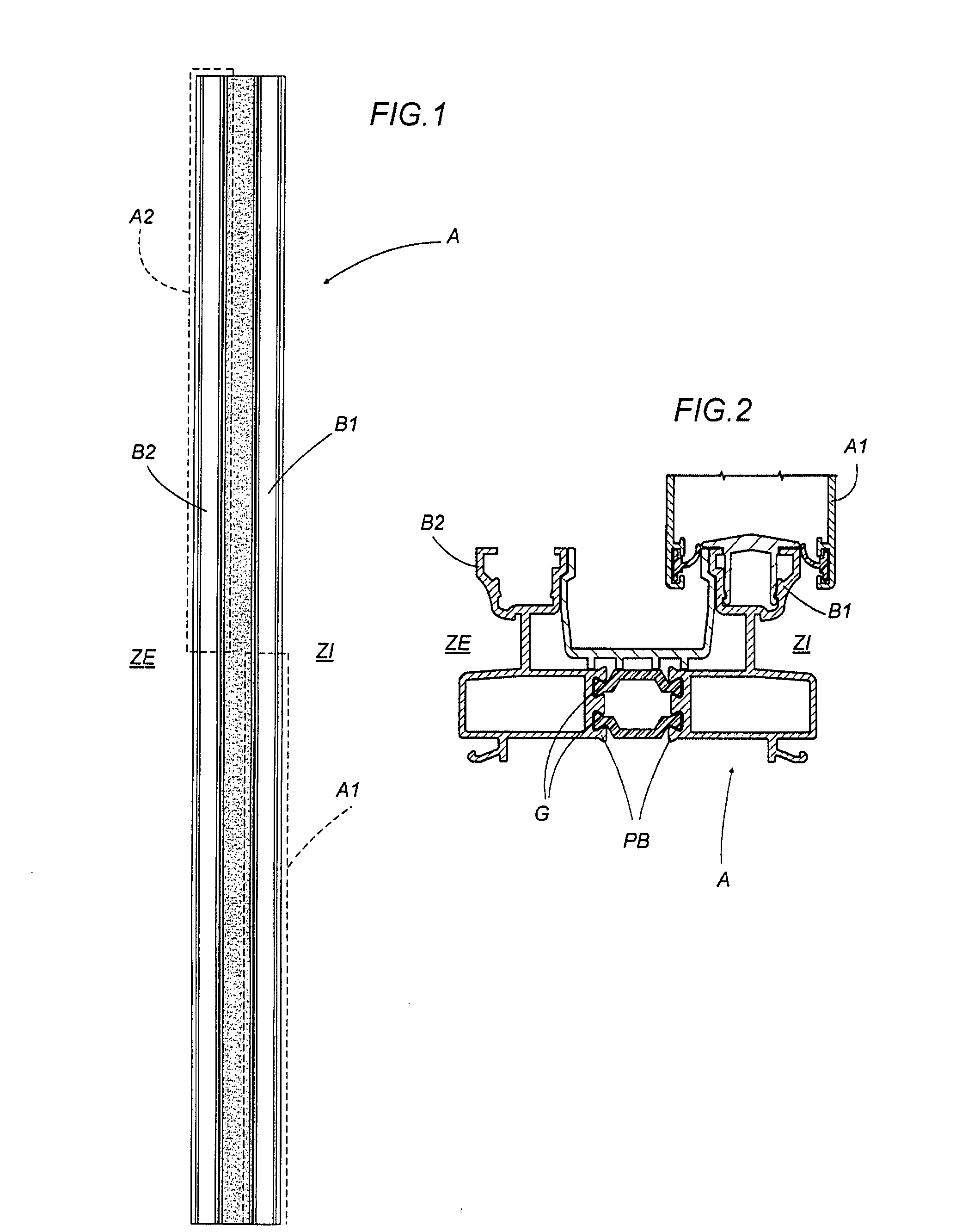
In the case of the sliding windows or doors (as clearly shown in FIGS. 1 and 2), this thermal break system on the frame does not allow acceptable performance to be achieved because the metal surfaces of the rails with faces common to the outside and inside, are never completely separate and so still allow the passage of heat by conduction from the inside to the outside and vice versa on the individual tracks even in the presence of the insulating bars forming the thermal break and the presence of seals on the two sides of the profile of the movable frames or sashes present which, in the closed position, are in contact with the tracks.
In addition to this the new energy saving regulations will make it difficult to use this type of window or door if its performance cannot be adjusted in terms of insulation.

Method used


Image

  • Profile for sliding windows or doors, method for making the profile, and window or door obtained with the profile
  • Profile for sliding windows or doors, method for making the profile, and window or door obtained with the profile
  • Profile for sliding windows or doors, method for making the profile, and window or door obtained with the profile

Examples


Embodiment Construction

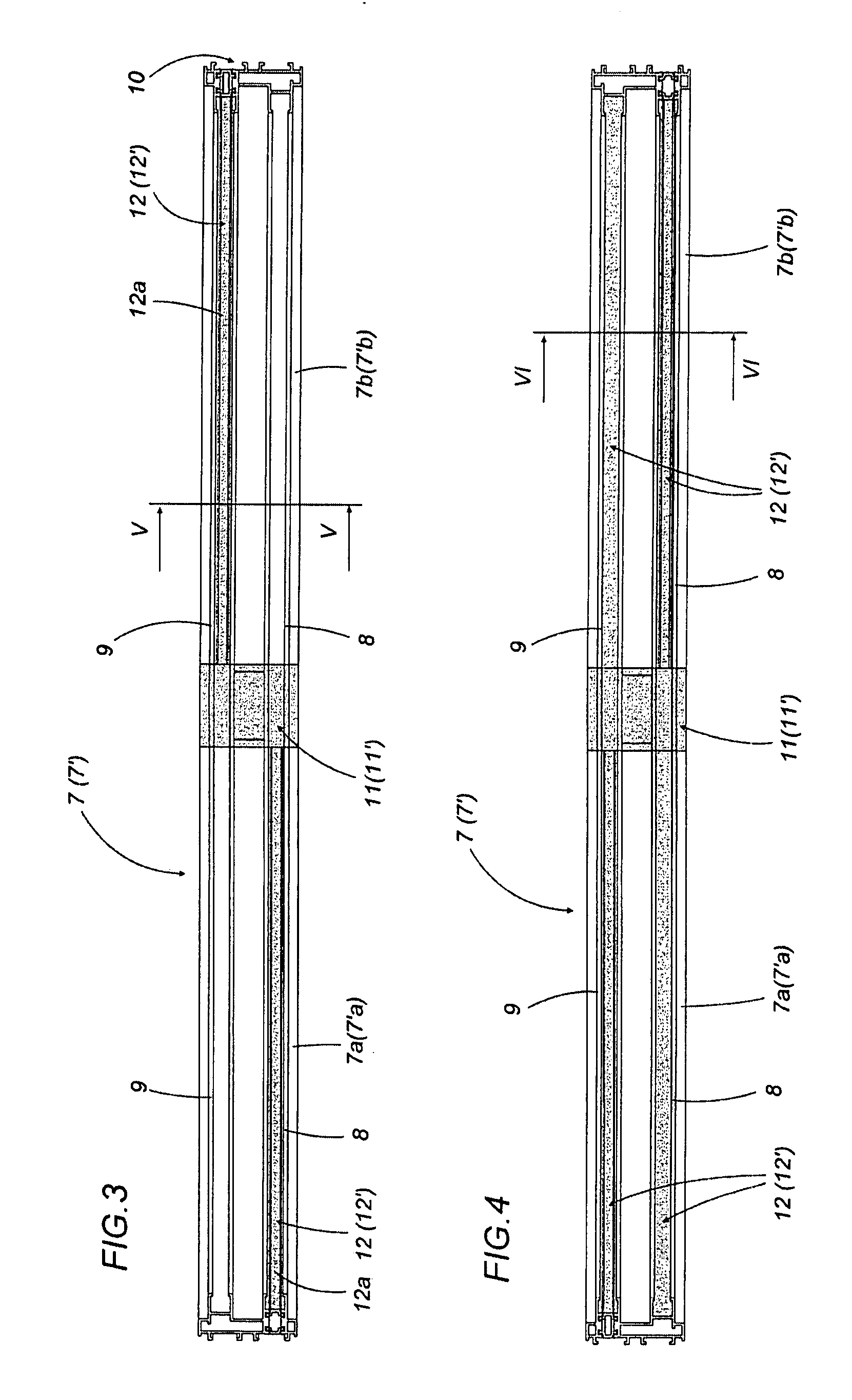
[0035]With reference to the accompanying drawings, and in particular with reference to FIGS. 3, 4 and 12, the profile, labeled 7 as a whole, is used to make frames for sliding windows or doors 1 comprising, amongst other things, at least one fixed frame 2 formed by two crosspieces 3 and 4 two stiles 5 and 6.

[0036]One of the profiles, labeled 7, forming at least a first lower crosspiece 3, comprises two sliding tracks 8 and 9, parallel with one another, and emerging from a lower base body 10.

[0037]As shown in FIGS. 3 to 6, this profile 7, forming the lower crosspiece 3, is divided, transversally, into two halves 7a and 7b substantially equal and associated, at respective ends, with a matching element 11 for connecting and joining the halves 7a, 7b.

[0038]The connecting and joining element 11 basically forms the central portion of the lower crosspiece 3 and has heat insulation properties (for example, it is made of a synthetic material, such as polyamide or in any case a material suit...


PUM

PropertyMeasurementUnit
Lengthaaaaaaaaaa
Heataaaaaaaaaa
Thermal propertiesaaaaaaaaaa

Abstract

A profile for making frames for sliding windows or doors comprising, amongst other things, at least one fixed frame formed by two crosspieces and two stiles; a profile, forming at least a first lower crosspiece, comprises two sliding tracks, parallel with one another, and made from a lower base body; the profile forming the lower crosspiece is divided, transversally, into two halves substantially equal and associated, at respective ends, with a matching element for connecting and joining the halves; the connecting and joining element therefore forming the central portion of the lower crosspiece and having heat insulation properties; the present invention also relates to a method for making the profile and a sliding window or door obtained with the profile.

Description

BACKGROUND OF THE INVENTION[0001]The present invention relates to a profile for sliding windows or doors, the method for obtaining this profile and the window or door which can be obtained with this profile.[0002]The sliding windows or doors usually consist of:[0003]a fixed frame (the most simple and usual versions also having a fixed sash positioned on a first track);[0004]at least one movable frame or sash which slides horizontally opening and closing relative to the fixed frame (parallel with the fixed sash);[0005]a pair of carriages, associated on the lower crosspiece of the movable sash and resting on a second horizontal track (parallel with the first track on which the fixed sash rests), and designed to allow the movable sash to slide in both directions;[0006]a control element positioned on the sash and designed to control operating means with which it is possible, respectively, to release the sash relative to the fixed frame and allow it to slide so that it opens, and to lock...

Claims


Application Information

Patent Timeline
IPC IPC(8): E06B1/04B21D47/00E04C2/38
CPCY10T29/49627E06B3/26347
Inventor LAMBERTINI, MARCO
Owner GSG INT
Learn More