
Vehicle Control System With Advanced Tire Monitoring

a technology of vehicle control system and tire monitoring, which is applied in the direction of brake system, cycle equipment, instruments, etc., can solve the problems of limited functionality of current tire pressure monitoring sensors, inability to discern coordinate acceleration data for wheels, and inability to monitor current tire pressure, etc., to improve vehicle ride and handling

Active Publication Date: 2008-10-02
FORD GLOBAL TECH LLC
View PDF18 Cites 109 Cited by
  • Summary
  • Abstract
  • Description
  • Claims
  • Application Information

AI Technical Summary

Benefits of technology

[0007]The suspension control system can include any one of an active suspension component for altering suspension geometry, a pneumatic cylinder adapted to adjust vehicle ride height, an adjustable suspension damper, or a central tire inflator adapted to adjust tire inflation. Thus, when the roadway surface condition estimation value indicates a rough surface, the suspension control system is adapted to soften the vehicle suspension characteristics. Conversely, when the roadway surface condition estimation value indicates a smooth surface, the suspension control system stiffens the vehicle suspension characteristics.
[0010]The embodiments of the present invention provide several advantages. One advantage provided by an embodiment of the present invention is a suspension control system that is capable of obtaining tire pressure and wheel acceleration knowledge and adjusting suspension control functions accordingly to improve vehicle ride and handling.

Problems solved by technology

Current tire pressure monitoring sensors, however, have limited functionality, and are not capable of discerning coordinate acceleration data for a wheel.

Method used


Image

  • Vehicle Control System With Advanced Tire Monitoring
  • Vehicle Control System With Advanced Tire Monitoring
  • Vehicle Control System With Advanced Tire Monitoring

Examples


Embodiment Construction

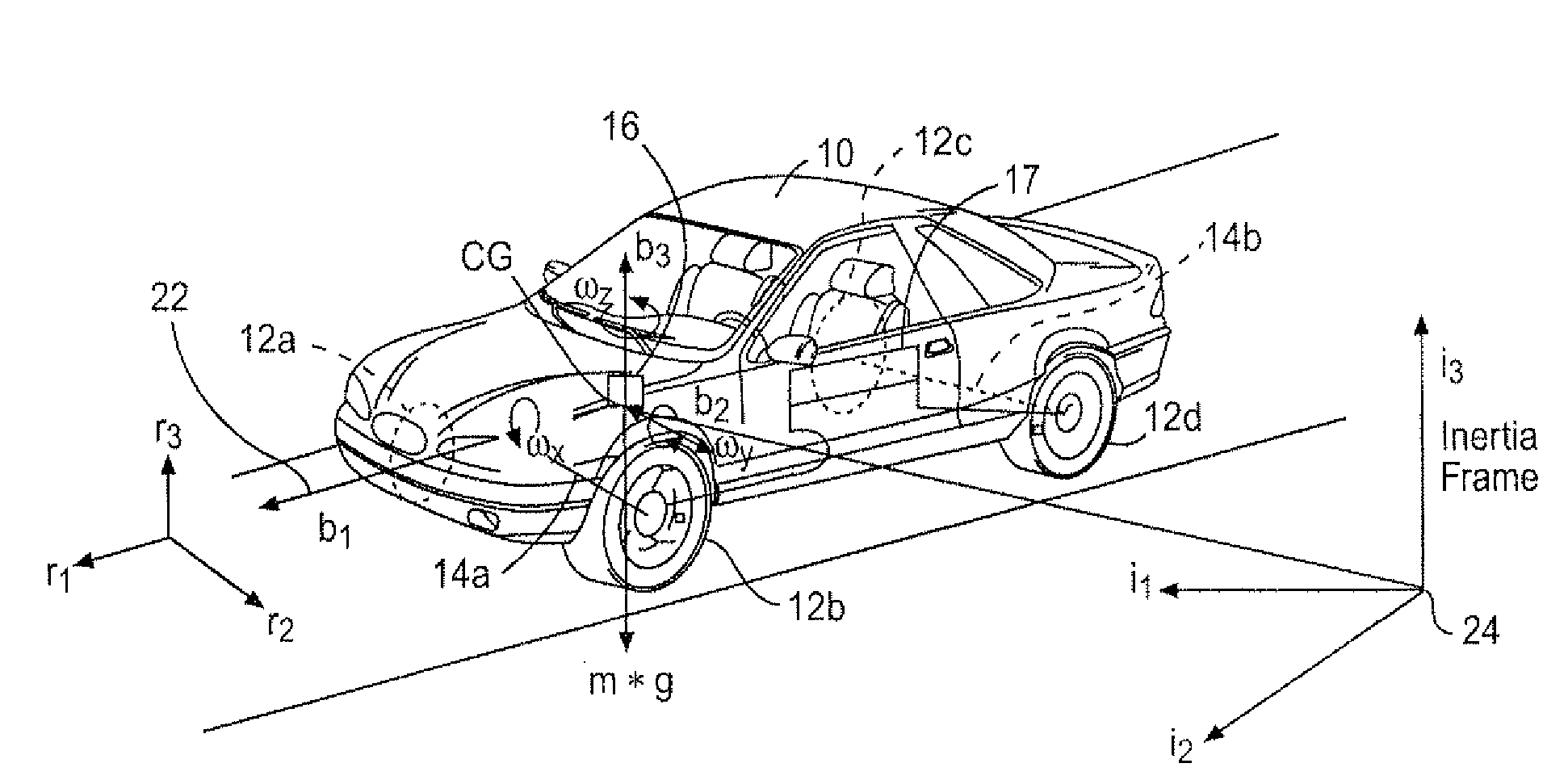
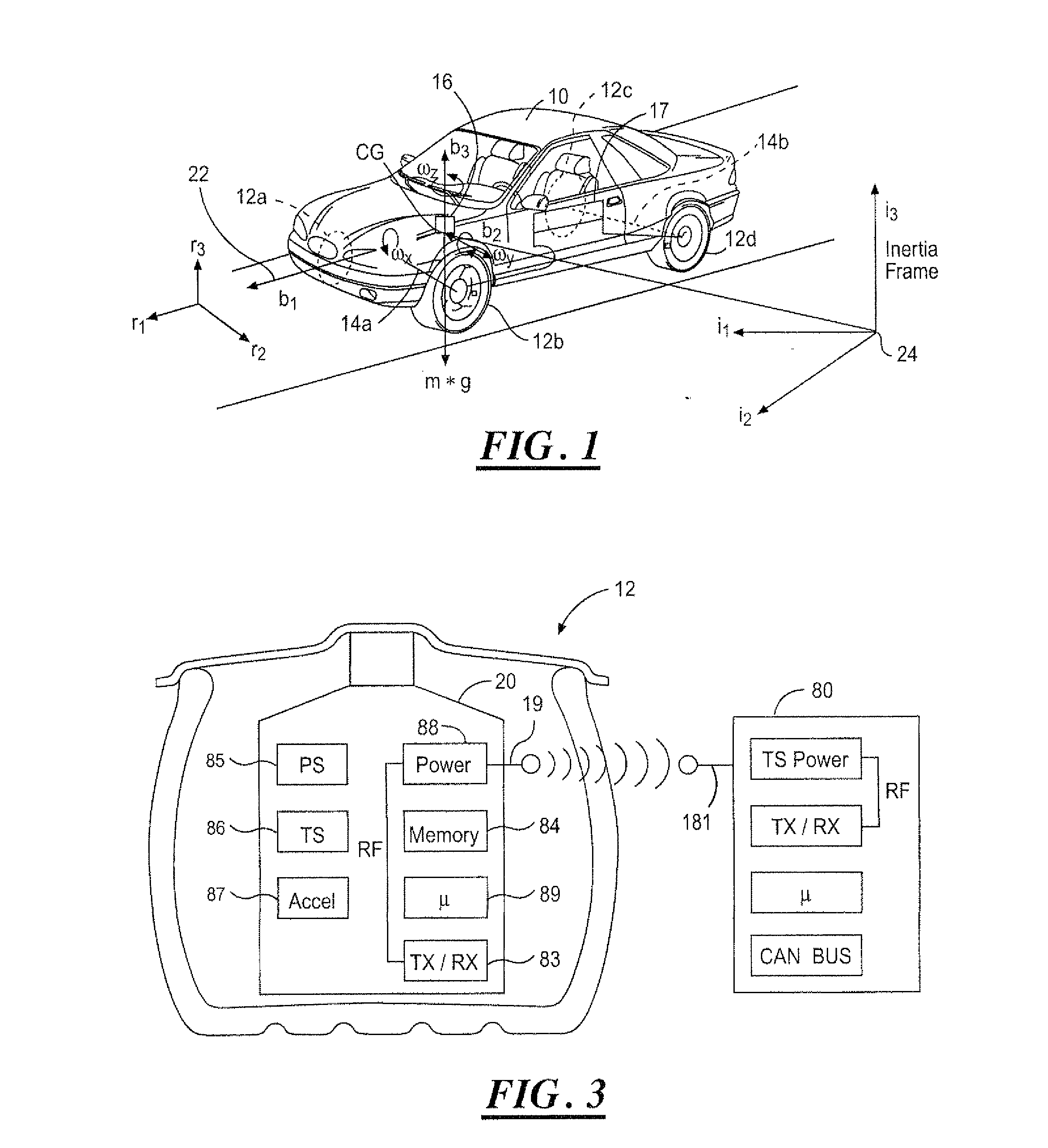
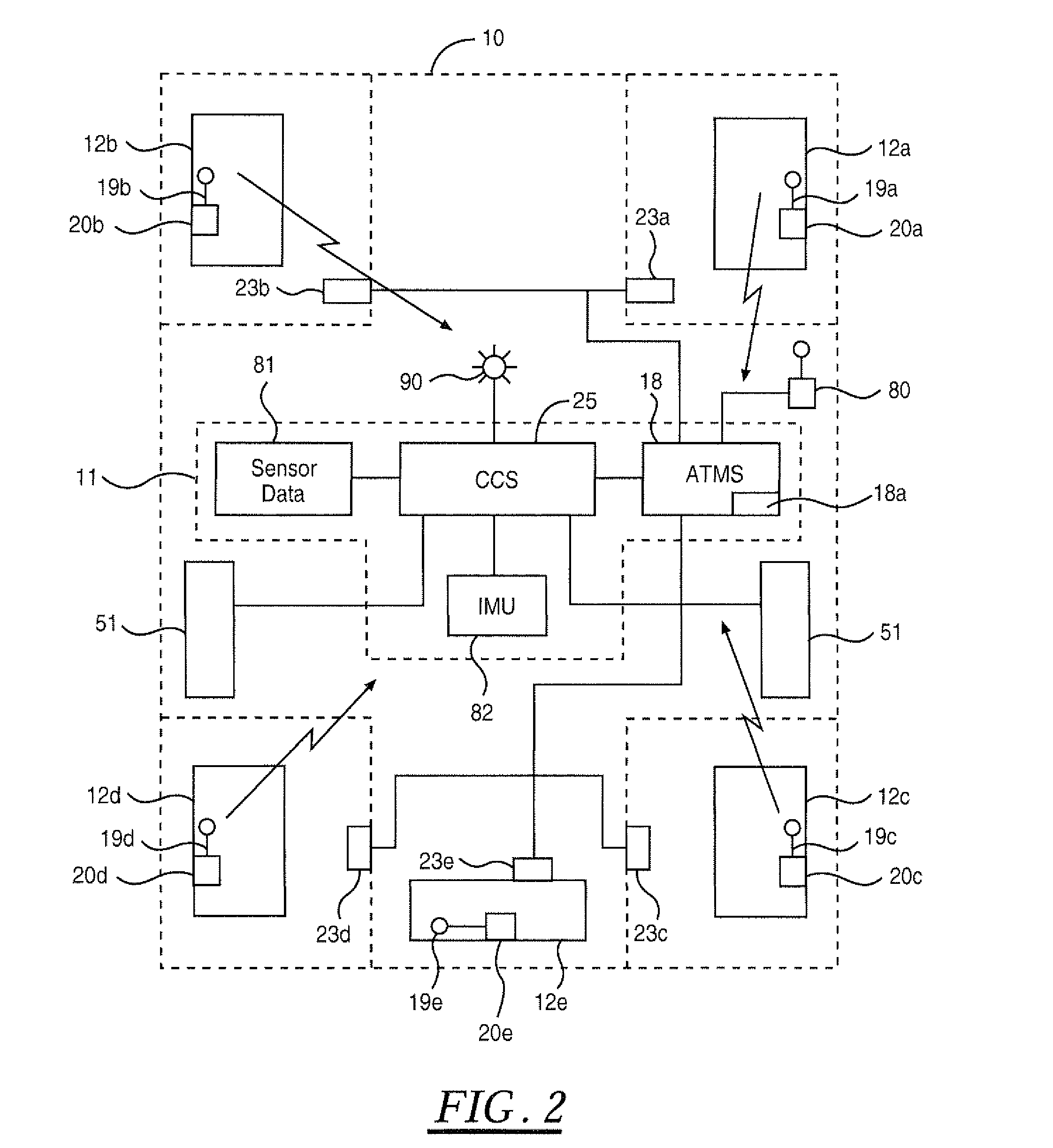
[0023]In the following figures, the same reference numerals will be used to identify the same components. The present invention may be used in conjunction with vehicle control systems including a yaw stability control (YSC) system, roll stability control (RSC) system, lateral stability control (LSC) system, integrated stability control (ISC) system, or a total vehicle control system for achieving desired vehicle performance. The present invention is also described with respect to an integrated sensing system (TSS), which uses a centralized motion sensor cluster such as an inertial measurement unit (IMU) and other available, but decentralized, sensors. Although a centralized motion sensor, such as an IMU, is primarily described, the techniques described herein are easily transferable to using the other discrete sensors.

[0024]In the following description, various operating parameters and components are described for several constructed embodiments. These specific parameters and compon...


PUM


Abstract

A control system (11) for a vehicle (10) includes vehicle dynamics sensors (35-47) providing a vehicle dynamics signal. Tire monitoring system sensors (20) in each wheel generate tire signals including temperature, pressure and acceleration data. A controller (26) communicates with the tire monitoring system sensors (20) and at least one vehicle dynamics sensor, and generates a roadway surface condition estimation value as a function of the multi-axis acceleration data of the tire signals. The roadway surface condition estimation value is transmitted to a suspension control system (33) to adjust the vevhicle suspension characteristics in response to the roadway surface condition estimation value.

Description

TECHNICAL FIELD[0001]The present invention relates generally to vehicle control systems and tire monitoring systems. More particularly, the present invention is related to vehicle control systems incorporating advanced tire monitoring for comfort and convenience.BACKGROUND[0002]Tire pressure monitoring may soon become a standard feature on vehicles. Current tire pressure monitoring sensors, however, have limited functionality, and are not capable of discerning coordinate acceleration data for a wheel. Conventional tire pressure sensors provide pressure and temperature sensing along with data processing and wireless communication of such data. Most also include a movement detection device such as switch or piezoelectric device that activates upon a radial acceleration. The movement detection devices “wake” the sensor to initiate data transmission, while saving battery life while the wheel is not moving.[0003]Advanced tire monitoring sensors (ATMS) are currently being developed. Besid...

Claims


Application Information

Patent Timeline
IPC IPC(8): B60G17/018
CPCB60G17/0165B60G17/018B60G17/019B60G17/0195B60G2400/0521B60G2400/0522B60G2400/0523B60G2400/102B60G2400/104B60G2400/204B60G2400/252B60G2400/33B60G2400/34B60G2400/39B60G2400/41B60G2400/44B60G2400/52B60G2400/60B60G2400/73B60G2400/821B60G2401/904B60G2600/04B60G2600/044B60G2600/18B60G2600/1882B60G2600/70B60G2800/162B60G2800/91B60G2800/912B60G2800/9124B60G2800/92B60G2800/984B60C23/002
Inventor BUJAK, CHRISTOPHER R.RAO, MANOHARPRASAD K.CUDDIHY, MARK A.
Owner FORD GLOBAL TECH LLC
Learn More