
Digital radio system and method of operation

a digital radio and radio system technology, applied in transmission systems, analogue/digital conversion, instruments, etc., can solve the problem of further reducing the computing power needed, and achieve the effect of substantially reducing or eliminating the disadvantages and problems of prior digital radio systems

Active Publication Date: 2008-10-02
CSR TECH INC
View PDF7 Cites 4 Cited by
  • Summary
  • Abstract
  • Description
  • Claims
  • Application Information

AI Technical Summary

Benefits of technology

[0003]In accordance with the present invention, the disadvantages and problems associated with prior digital radio systems have been substantially reduced or eliminated.
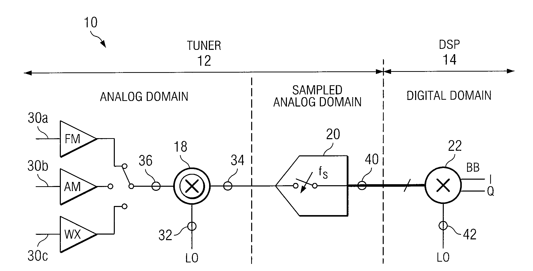
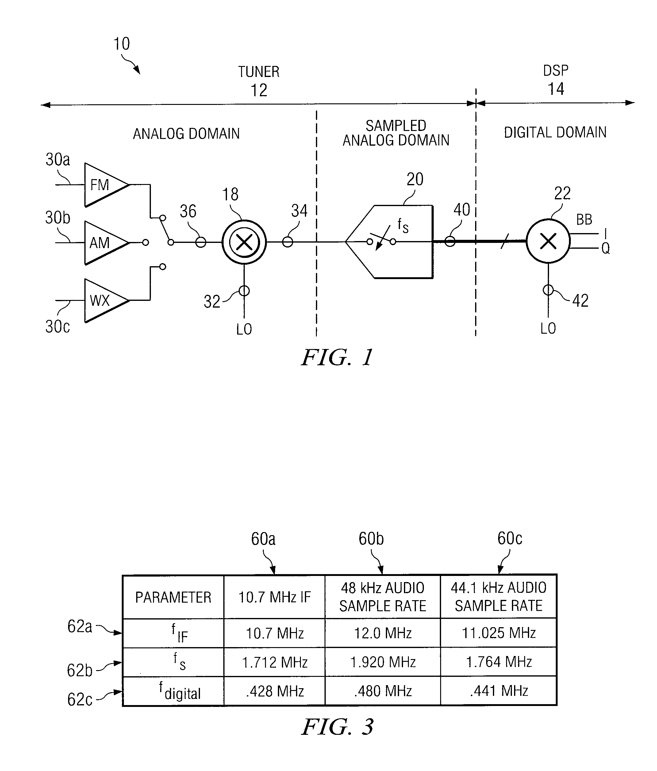
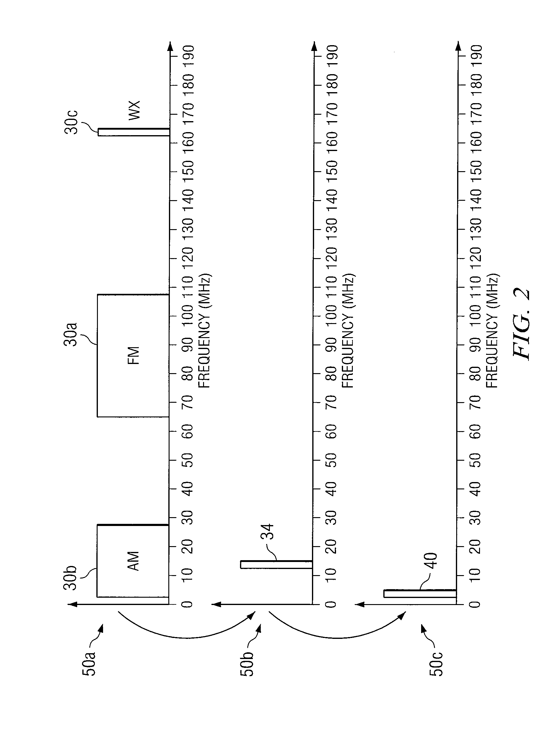
[0006]The following technical advantages may be achieved by some, none, or all of the embodiments of the present invention. Particular technical advantages of the present invention are achieved because the tuner of the digital radio system adopts a particular sampling approach when digitizing the intermediate frequency signal. In particular, the analog-to-digital converter quantizes the intermediate frequency signal using a sampling frequency that is greater than twice the bandwidth of the signal of interest and less than the frequency of the intermediate frequency signal. A result, in one embodiment, is that the frequency of the digital signal is one quarter of the sampling frequency. In this regard, the sampling frequency is selected in such a way that the subsequent baseband conversion can be realized without complex frequency mixing. In particular, the baseband conversion can be achieved with simple multiplication (e.g., for I: 1, −1, −1, and 1; and for Q: 1, 1, −1, −1; or, alternatively, for I: 1, 0, −1, and 0; and for Q: 0, 1, 0, and −1), thereby reducing the computing power necessary in the digital signal processing (DSP) circuitry. Furthermore, in one embodiment, the data rate is an integer multiple of standard audio sample rates like 48 kHz or 44.1 kHz, which reduces the necessary computing power even further. This results in power savings in the DSP and enables implementation of an AM / FM / WX radio using an “off the shelf” DSP.

Problems solved by technology

Furthermore, in one embodiment, the data rate is an integer multiple of standard audio sample rates like 48 kHz or 44.1 kHz, which reduces the necessary computing power even further.

Method used


Image

  • Digital radio system and method of operation
  • Digital radio system and method of operation
  • Digital radio system and method of operation

Examples


Embodiment Construction

[0013]FIG. 1 illustrates a simplified block diagram of a digital radio system 10 comprising a tuner block 12 and a digital signal processing (DSP) block 14. Tuner block 12 comprises a mixer 18 and an analog-to-digital converter (ADC) 20. DSP block 14 comprises a mixer 22. In general, the digitization performed by ADC 20 is performed using a bandpass sampling approach so that the subsequent baseband conversion performed by DSP block 14 can be performed on the digital signal without the need for complex frequency mixing. In this regard, an AM / FM / WX radio can be implemented using an “off the shelfdigital signal processing circuit.

[0014]A mixer comprises a circuit element that performs frequency translation of a broadband signal to an intermediate frequency (IF) signal, or from an IF signal to a baseband signal, or from a broadband signal to a baseband signal. For example, a mixer may comprise a bolometer, photoconductor, Schottky diode, quantum non-linear device (e.g. SIS receiver or...


PUM


Abstract

A digital radio system comprises a mixer and an analog-to-digital converter communicative coupled to the mixer. The mixer generates an intermediate frequency signal based at least in part upon a radio frequency signal and a local oscillator signal, wherein the intermediate frequency signal comprises a signal of interest having a particular bandwidth. The analog-to-digital converter generates a digital signal by quantizing the intermediate frequency signal using a sampling frequency that is greater than twice the bandwidth of the signal of interest and less than the frequency of the intermediate frequency signal.

Description

TECHNICAL FIELD OF THE INVENTION[0001]This invention relates in general to signal processing, and more particularly to a digital radio system.BACKGROUND OF THE INVENTION[0002]Current AM / FM radio tuners perform a series of frequency conversions from the radio frequency signal to a first intermediate frequency signal and then to a second intermediate frequency signal. The second intermediate frequency signal is then sampled and digitized at a high rate using an oversampling approach. The digital signal is then filtered and converted to a baseband frequency using hardware based filters and digital mixers. However, “off the shelfdigital signal processing circuitry cannot be used to perform the baseband conversion because it is unable to handle the high data rate of the digital signal resulting from the oversampling of the second intermediate frequency.SUMMARY OF THE INVENTION[0003]In accordance with the present invention, the disadvantages and problems associated with prior digital ra...

Claims


Application Information

Patent Timeline
IPC IPC(8): H03M1/12
CPCH04B1/28H04B1/406
Inventor VOLNHALS, STEFAN
Owner CSR TECH INC
Learn More