
Modular Concrete Wall System

a concrete wall and modular technology, applied in the field of components, can solve the problems of deteriorating wood past, physical labor of laying cinder blocks, and affecting the aesthetics of finished surfaces, and achieve the effect of quick and convenient assembly

Inactive Publication Date: 2008-10-02
BANOVA ALDO
View PDF22 Cites 5 Cited by
  • Summary
  • Abstract
  • Description
  • Claims
  • Application Information

AI Technical Summary

Benefits of technology

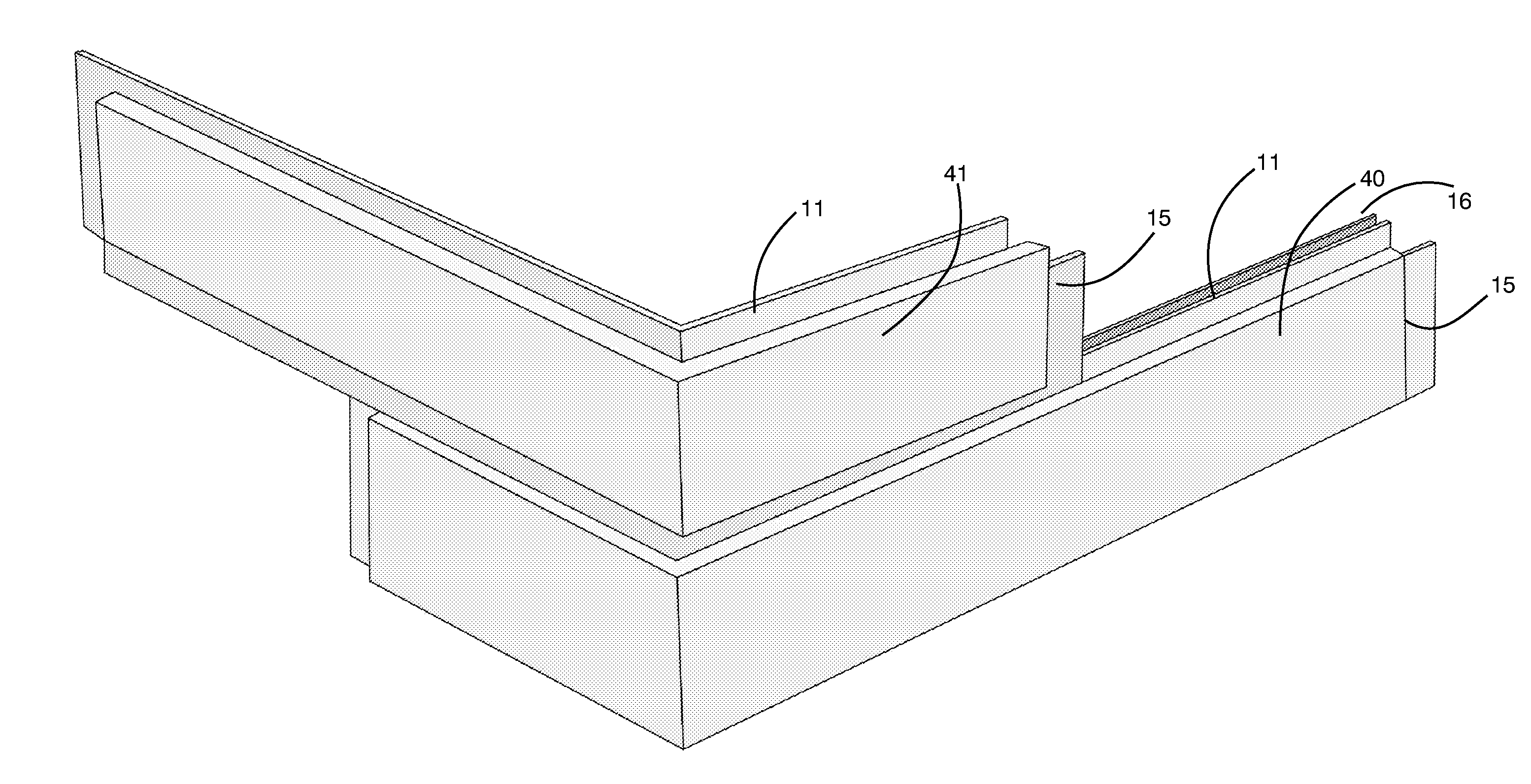
[0013]Thus, a metal footer track assembly as described in this disclosure is affixed to a standard concrete footer or foundation. Then the modular metal forms of the present invention are assembled upon the footer track, stacked together in such a way as to produce the appearance of a brick wall. With every few rows of modular metal forms, such as two rows, the forms are filled with poured concrete. Following the concrete pour, additional metal forms are assembled on the top of the previous forms, to produce about two additional rows, and more concrete is then poured again. By repeating this process, the full height of the wall can be quickly reached. The method lends itself readily to inclusion of steel rebar, such as for horizontal bond beams and for vertical members as well.OBJECTS OF THE INVENTION
[0014]It is an object of the present invention to provide a strong poured concrete wall system that will produce an aesthetically pleasing brick wall appearance.
[0015]It is another object of the present invention to provide a system where the forms can be rapidly assembled, without the cost of skilled labor, and where the need for physical strength and stamina in the laborer presently required for stacked cinder block methods is significantly reduced.
[0016]It is another object of the present invention to produce an affordable poured concrete wall system that eliminates the costs associated with the labor in removing the modular forms, of cleanup, and also the costs associated with disposing of the forms, including the burden upon municipal landfills.
[0017]It is also an object of the present invention to afford a concrete wall system that has the excellent fire resistant properties of metal and concrete construction materials, and produces a stronger wall than other methods.
[0018]It is also an object of the present invention to afford a concrete wall system where the modular forms are more compact, and therefore less expensive to transport and store.

Problems solved by technology

Such wooden forms may be re-used once or twice, but soon the repeated exposure to poured concrete deteriorates the wood past the point of serviceability, and the wood forms must be removed from the jobsite and discarded.
Additionally, steel-reinforced poured concrete, while strong, tends to leave a finished surface with little aesthetic appeal.
However, laying cinder blocks is physically taxing, often requiring the services of an unskilled laborer to port them, and also requires the use of a skilled mason to properly align and set each block.
Thus laying bricks and blocks is a difficult, time-consuming, and labor intensive procedure.
This method requires the removal of the forms, and is time consuming in its application.
This art does not avoid the use of rather have masonry units however, and although it saves time over other prior art, it remains labor intensive.
This construction of the mold involves several steps, which like the wooden forms must be removed and is subject to deterioration upon repeated use and subsequently disposed of.

Method used


Image

  • Modular Concrete Wall System
  • Modular Concrete Wall System
  • Modular Concrete Wall System

Examples


Embodiment Construction

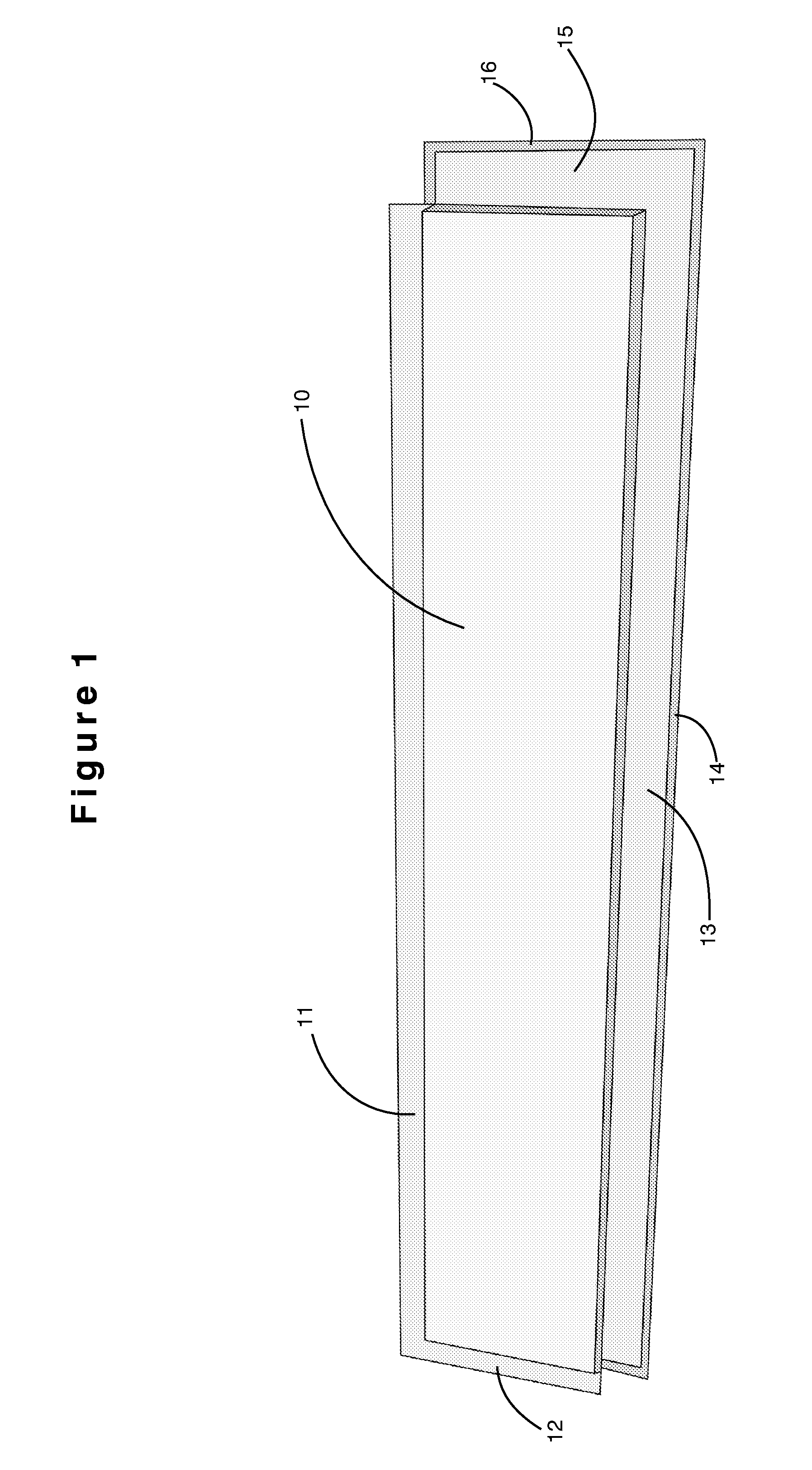
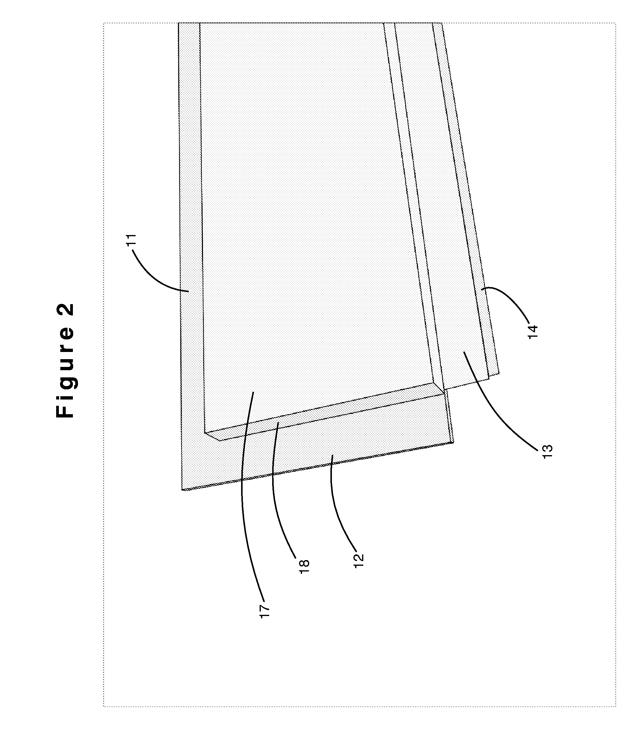
[0031]Referring to the drawings in detail, wherein like numerals indicate like elements, FIG. 1 illustrates a basic modular form unit 10 as part of the concrete wall system in accordance with the present invention. This basic modular form unit 10 provides the outside face of a single “brick”. A plurality of the basic modular form units 10, along with other special purpose adaptations of the basic modular form unit, are assembled together to produce the overall wall system. The basic modular form unit 10 is fabricated out of metal of suitable properties and thickness. The basic modular form unit is approximately rectangular with flanges at each end, and at the top and bottom edges as well. In FIG. 1 there is shown a top single flange 11 that runs the length of the modular form unit. It is continuously connected to the single flange 12 on the left end of the basic modular form unit 10. The single flanges 11 and 12 are parallel to the surface of the rectangular area of the basic modula...


PUM

PropertyMeasurementUnit
widthaaaaaaaaaa
widthaaaaaaaaaa
widthaaaaaaaaaa

Abstract

Disclosed is a modular poured concrete wall system that addresses the needs not optimally met by the prior art, where inexpensive small light interlocking forms are quickly and readily assembled, to produce the desired aesthetically pleasing appearance of a brick wall system. The forms remain in place as part of the final structure and finished surface of the walls. Thus, a footer track assembly is affixed to a standard concrete footer or foundation. Then the modular forms are assembled upon the footer track, stacked together to produce the appearance of a brick wall. As each row or two of forms are assembled, the forms are filled with concrete. Following the concrete pour, additional forms are assembled on the top of the prior forms, to produce additional rows. By repeating this process, the full height of the wall can be quickly reached. The method may include steel rebar, such as for horizontal bond beams and for vertical strength. In an alternative embodiment, curved modular forms may be assembled to produce a circular column, where the exterior surface is finished as a decorative brick appearance.

Description

CROSS REFERENCE TO RELATED APPLICATIONS[0001]Not applicable.STATEMENT REGARDING FEDERALLY SPONSORED RESEARCH OR DEVELOPMENT[0002]Not applicable.REFERENCE TO MICROFICHE APPENDIX[0003]Not applicable.FIELD OF THE INVENTION[0004]This invention relates to a system of components and a method of use for creating a concrete wall system.BACKGROUND OF THE INVENTION[0005]Conventional masonry walls are typically built of poured concrete or stacked cinder or concrete blocks or bricks. These two types of construction, poured concrete and block, are used additionally for walls in commercial buildings, such as warehouses and hotels, and in residential homes. In preparing concrete walls for structural walls, a support element is needed to retain the concrete while it hardens. The support element conventionally takes the form of wooden form boards and steel bracing to retain the concrete wall as it hardens. The wooden forms are removed from the site once the concrete hardens. Such wooden forms may be...

Claims


Application Information

Patent Timeline
Patent Type & Authority Applications(United States)
IPC IPC(8): E04B2/40
CPCE04B2/8635E04B2002/867Y10T29/49631Y10T29/49629E04C3/34
Inventor BANOVA, ALDO
Owner BANOVA ALDO
Learn More